
Electrical Measurement & Monitoring · Selection Guide
Digital Panel Meter Selection Guide: Function, Range, Panel Cutout and Model Verification
Selecting a digital panel meter begins with the measurement and installation requirements, not with the display appearance alone. Buyers should define the required function, measurement range, panel opening, available depth, operating supply, input arrangement, accuracy requirement, communication needs and exact model documentation before ordering.
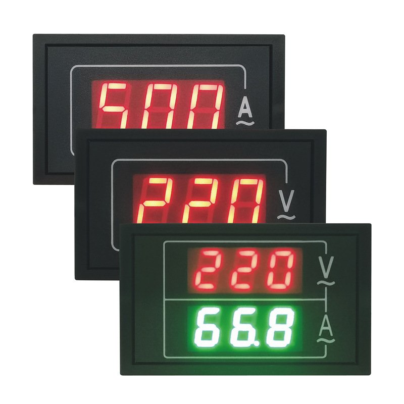
This digital panel meter selection guide separates general verification steps from published RITOKS product facts. It does not calculate a measurement range, determine a current-transformer ratio, design wiring or automatically recommend a model.
Digital Panel Meter Selection at a Glance
A practical specification moves from measurement function and range to physical fit, electrical inputs, communication and documentation. Official technical resources such as the Schneider Electric DM6000 installation guide and its GoLogic digital panel meter instruction sheet illustrate why installation and model documentation must be checked for a specific meter. The Modbus Organization serial-line specification distinguishes the Modbus protocol stack from physical interfaces such as RS485. These references support general concepts only; their specifications, protocols and certifications are not RITOKS product data.
Digital Panel Meter Selection Inputs
| Selection input | What to define or verify |
|---|---|
| Measurement function | Voltage, current, combined voltage/current or multifunction measurement requirement |
| Measurement range | Required range and the exact published model option |
| Display | Required display type, layout and color where applicable |
| Panel dimensions | Available front-panel area and exact product dimensions |
| Cutout / mounting hole | Existing or planned opening against the exact published requirement |
| Installation depth | Available cabinet depth, clearances and mounting arrangement |
| Operating supply | Required supply and the exact model specification |
| Input configuration | Required voltage/current input arrangement and phase configuration |
| External CT requirement | Whether a CT or another input arrangement is required for the exact model |
| Accuracy | Project requirement and the exact published model field |
| Communication interface | Required physical communication interface, if any |
| Communication protocol | Required protocol, settings and documentation confirmed separately |
| Exact model | Complete orderable configuration and model-specific data |
| Wiring / documentation | Exact wiring diagram, datasheet and required supporting documents |
1. Start With the Measurement Function
Voltage Meter
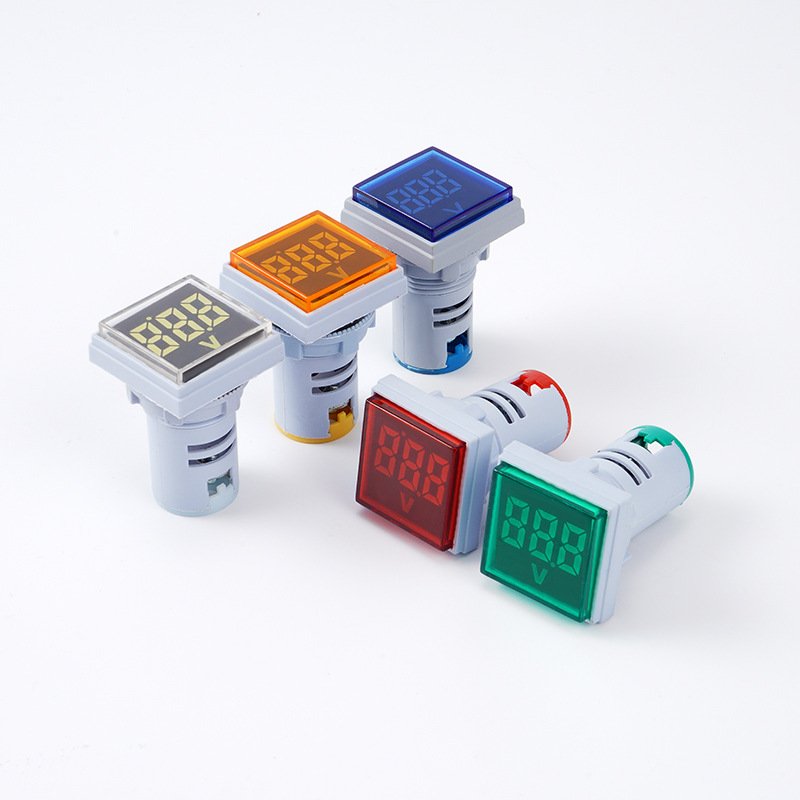
A voltage meter displays the voltage parameter published for its selected configuration. Define the required system measurement and range, then verify the exact input, supply and wiring documentation. The D85-V is the voltmeter version in the D85 AC digital voltage and current panel meter family. The AD16-22 is a separate compact voltage-display format; neither product should inherit electrical data from the other.
Current Meter
A current-meter requirement should identify the expected measurement range and the input arrangement required by the connected system. D85-A is the published ammeter version of the D85 family. Its listed current options do not establish whether a particular unit is directly connected, uses an external CT, contains another sensing arrangement or includes any accessory. Those details require exact model documentation.
Combined Voltage / Current Meter
A combined meter presents voltage and current functions in one panel format. D85-5035VA is the confirmed combined voltage/current configuration. Buyers still need to verify both applicable ranges, the input arrangement, supply and wiring. A combined display is not the same as a multifunction energy or power meter.
Multifunction Meter
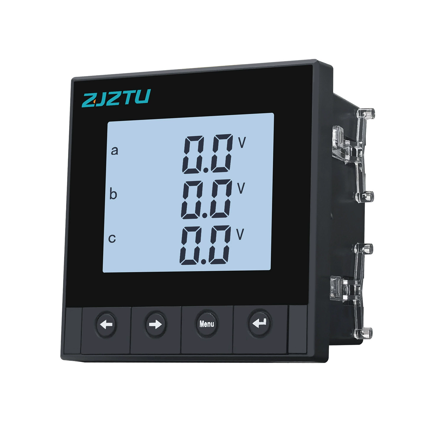
A multifunction meter may consolidate several published electrical measurement functions. The RITOKS single/three-phase multifunction digital power meter with RS485 currently publishes multifunction power-parameter measurement, energy-metering wording, programmable settings and sixteen listed configurations. These statements do not establish unlisted functions such as harmonics, demand, tariff features or power-quality analysis.
2. Confirm the Measurement Range
Define the required voltage or current range from the project and compare it with the exact published model. The D85 family publishes 60–500V AC where applicable and 0–100A AC or a supplier-listed 0–160A AC option where applicable. D85-V also retains a separately supplier-stated 600V maximum measurable voltage, which is not presented as its regular range.
The current pages do not publish complete electrical ranges for every multifunction configuration, and the AD16-22 page does not publish a voltage range. Do not apply a universal headroom rule, infer overload capability or choose the next larger range automatically. Missing range data should be requested for the exact model.
3. Check Panel Size and Cutout
Panel fit requires more than the visible front dimensions. Confirm the product dimensions, cutout or mounting-hole requirement, installation depth, retaining method and available cabinet space. D85 publishes overall dimensions of 70 × 42 × 25 mm and a 68 × 38 mm panel cutout. AD16-22 publishes a 22 mm mounting hole but not complete body dimensions.
The multifunction family lists panel-size options of 76 × 76 mm, 86 × 86 mm and 96 × 96 mm, together with cutout options of 66 × 66 mm, 76 × 76 mm and 91 × 91 mm. The current evidence does not map every panel size and cutout one-to-one across all sixteen configurations, so buyers should confirm the selected configuration rather than freely combining those values.
4. Confirm Supply and Input Configuration
The meter operating supply and its measurement inputs are separate fields to verify. The current RITOKS pages do not provide a complete supply and input map for every D85 or multifunction configuration, and AD16-22 does not publish its supply or AC/DC measurement type. Request the exact electrical specification before design-in.
Do not derive terminal assignments, phase/neutral connections or supply wiring from a product image. A model name, displayed range or phase description is not a wiring diagram. Installation should follow the documentation supplied for the exact configuration.
5. Verify Current and CT Requirements
Some current-measurement applications may require an exact input or CT configuration to be confirmed from model documentation. The published D85 current ranges do not establish direct connection, an external CT requirement, an internal CT, a supplied CT or any particular wiring topology. The multifunction page likewise does not publish a complete CT/input arrangement for every configuration.
Specify the system requirement and ask which exact meter input configuration applies. Do not select a CT ratio from this article, automatically pair a meter with a RITOKS current transformer or assume a 5A secondary input without model-specific evidence.
6. Check Communication Interface and Protocol Separately
An RS485 interface does not by itself identify the application protocol used by a specific meter. RS485 describes an available serial interface, while the protocol and its settings must be stated separately in exact model documentation. This distinction matters when an RFQ requires integration with another device or monitoring system.
Product 424 publishes RS485 and supplier-stated dual-protocol support, but the current page does not publish the protocol names. It therefore must not be described as supporting Modbus, MODBUS-RTU, DL/T645 or any register map, baud rate, parity or address range. State the required protocol in the inquiry and request confirmation for the selected configuration.
7. Verify Accuracy and Exact Electrical Data
Accuracy is a project field to define and an exact-model field to verify. The multifunction family carries a supplier-stated Class 0.5 statement, but the current evidence does not map that statement independently to every listed configuration. Accuracy is not published for D85 or AD16-22 on their current pages.
Do not treat a lower numerical class as a universal performance ranking or infer billing, revenue-metering, legal-metrology or protection suitability. Frequency, input impedance, operating conditions, supply, wiring and supporting documentation should also be confirmed wherever the project requires them.
Published RITOKS Digital Panel Meter Families
The Digital Panel Meters category is part of Electrical Measurement & Monitoring. The overview below supports initial family screening; it is not a performance ranking or an automatic recommendation.
Published RITOKS Digital Panel Meter Family Overview
| Family | Published function | Published range information | Panel / mounting information | Communication / accuracy | Key data to confirm |
|---|---|---|---|---|---|
| D85 | Combined voltage/current, voltmeter and ammeter versions | Applicable 60–500V AC; applicable 0–100A AC or supplier-listed 0–160A option; D85-V separately states 600V maximum | 70 × 42 × 25 mm; 68 × 38 mm cutout | Not published | Supply, input/CT arrangement, wiring, frequency, accuracy, impedance and documentation |
| Multifunction RS485 family | Sixteen listed single/three-phase multifunction, ammeter and voltmeter configurations; power-parameter measurement, energy metering and programmable settings | Complete exact electrical ranges not published | Published panel and cutout options; complete one-to-one mapping not published | RS485 published; named protocol not published; supplier-stated Class 0.5 | Exact ranges, supply, input/CT arrangement, wiring, protocol, dimensions, accuracy mapping and documentation |
| AD16-22 | LED digital voltage display; five display colors | Not published | 22 mm mounting hole; complete dimensions not published | Not published | Voltage range, supply, AC/DC type, frequency, accuracy, wiring and documentation |
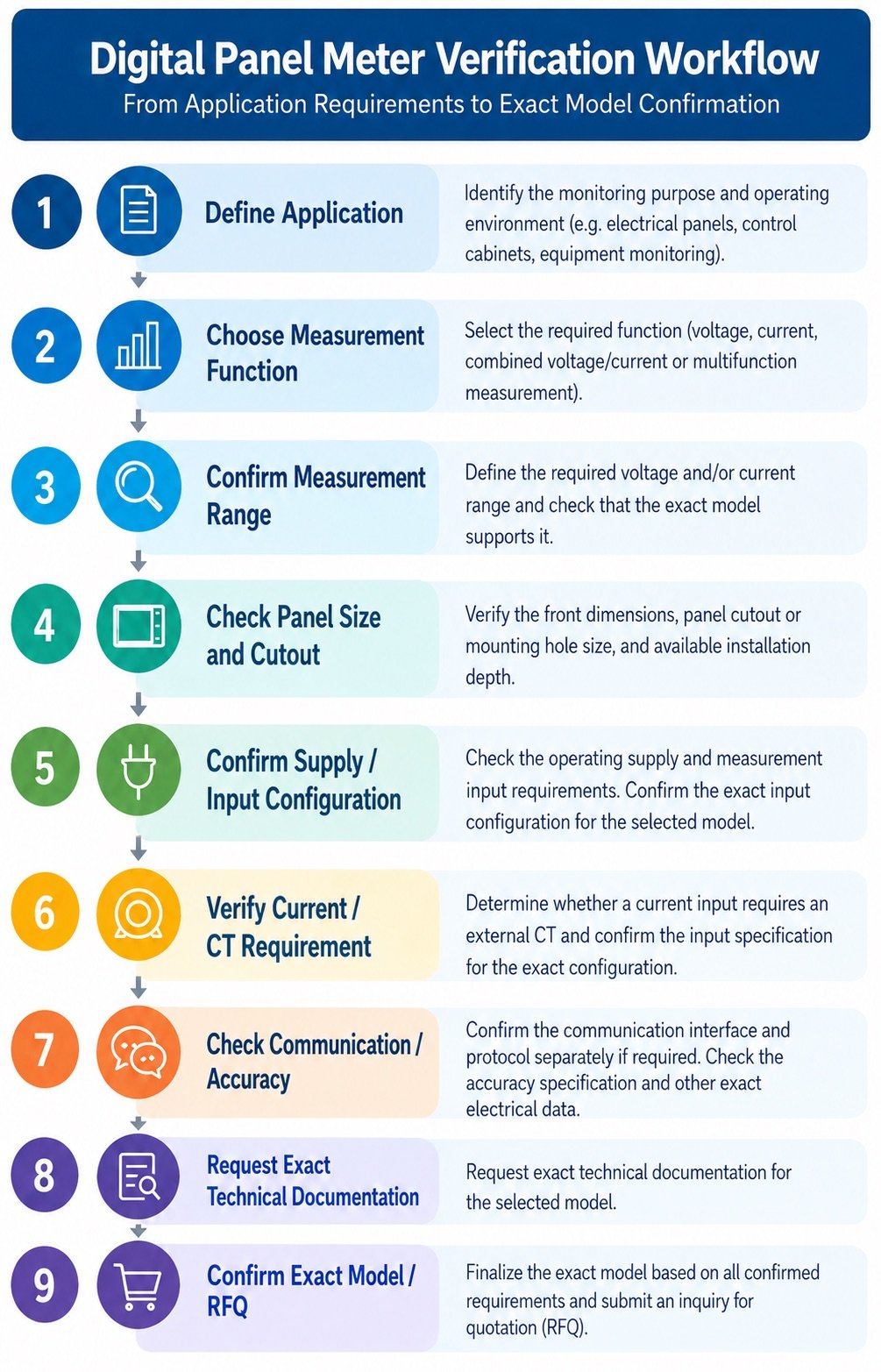
8. Exact-Model Verification Workflow
9. Information to Include in a Digital Panel Meter Inquiry
- Application and parameters to be displayed or measured
- Required voltage and current ranges
- Single-phase or three-phase requirement, if applicable
- Display type and format
- Available panel area, cutout or mounting-hole size and installation depth
- Required operating supply and input configuration
- Current-transformer requirement or meter input requirement, if applicable
- Accuracy requirement, if applicable
- Required communication interface and named protocol
- Quantity and destination
- Required datasheet, wiring diagram and other documentation
10. What Data Still Requires Exact-Model Confirmation?
Exact-model confirmation is required wherever the current page does not publish a complete electrical range, operating supply, input arrangement, CT requirement, wiring, frequency, accuracy mapping, protocol, dimensions or supporting document. A missing field must not be filled from a similar meter, a product image or another RITOKS family.
Frequently Asked Questions
What should I check before selecting a digital panel meter?
Define the measurement function and range, panel fit, supply, input arrangement, accuracy, communication requirements and exact documentation needed for the project.
What is the difference between a voltmeter, ammeter and multifunction meter?
A voltmeter measures a published voltage parameter, an ammeter measures a published current parameter, and a multifunction meter combines several published electrical measurement functions. Exact capabilities remain model-specific.
Can I select a panel meter from measurement range alone?
No. Function, input configuration, supply, physical fit, accuracy, communication and wiring documentation may also affect the exact model choice.
Does RS485 mean a meter supports Modbus?
No. RS485 identifies an interface. Protocol support must be confirmed separately for the exact model and configuration. Product 424 does not currently publish a named protocol.
Do all RITOKS current meters use an external CT?
No such family-wide conclusion is supported. Confirm whether the exact meter uses a direct input, external CT or another input arrangement from its model documentation.
Is Class 0.5 published for every RITOKS panel meter?
No. The multifunction family has a supplier-stated Class 0.5 statement. Accuracy is not currently published for D85 or AD16-22, and exact configuration applicability should be confirmed.
What information should I provide for exact-model confirmation?
Provide the required function, ranges, phase arrangement, panel fit, supply, input or CT requirement, accuracy, interface and protocol requirements, quantity, destination and required documentation.
Confirm the Exact Digital Panel Meter for Your Project
Send RITOKS your measurement, range, panel-fit, input, communication and documentation requirements for exact-model review.
Related Resources
Continue exploring Electrical Measurement & Monitoring
DIN Rail Energy Meter Selection Guide: Phase, Current, Communication and Model Verification
Selecting a DIN rail energy meter starts with the electrical and monitoring requirements, not with a current marking…
Read guide
Current Transformer Selection Guide: Construction, Ratio, Output and Model Verification
Selecting a current transformer starts with the measurement requirement, not with a model number alone. Buyers should define…
Read guide