
DC Power Protection · Technical Explainer
Battery-to-Inverter Protection Boxes: Agree the Interface Before Ordering
Quick answer
A battery-to-inverter protection box is not fully specified by its enclosure size and circuit count. The useful purchasing boundary is the interface between the battery supplier, box manufacturer, cable assembler and inverter integrator. Each party needs to know which drawing controls its work, which terminals it is responsible for, and which protective functions remain outside its delivery.
Agree the power terminals, external cable scope, separate communication and earth requirements, and the owner of every required protective function before ordering. A proposal with fewer included items can be acceptable if another named party supplies them; a more complete-looking box can remain unsuitable when its interfaces or duties lack evidence.
Connect the circuit diagram to the terminal schedule, cable drawings, exact internal component list and equipment manuals. This is a document-review framework, not an installation procedure or an approved battery wiring diagram. Electrical design and commissioning remain tasks for qualified personnel using the selected equipment instructions.
Start with the complete system boundary
An interface agreement should describe what enters the box, what leaves it and what is supplied elsewhere. Without those boundaries, two suppliers can each deliver a correct component while leaving an incomplete system. The purchasing record must therefore identify physical connections and ownership together, rather than treating the enclosure as a self-contained solution.
Start with a current one-line diagram supplied by the responsible system designer. Give the drawing a revision and identify the battery equipment, inverter equipment and proposed box. Record the operating modes that the drawing represents. A diagram prepared only for normal discharge might leave charging, a maintenance state or an alternative source outside its scope.
Create a separate boundary list for auxiliary power, monitoring, communication and mechanical support. Do not assume that every line visible in an illustration belongs in the quoted power box. A cable depicted between an inverter and battery controller could be part of another supplier's harness rather than an internal enclosure connection.
Treat these questions as purchasing tasks. The goal is to obtain an agreed scope for engineering, not to decide conductor arrangements from a blog. Where suppliers disagree, record the disagreement against the drawing and assign an owner to resolve it before fabrication.
Build a terminal and cable interface sheet
A terminal sheet is useful when it removes ambiguity about identities, viewing directions and supplied parts. It should describe the exact connection boundary without becoming an improvised wiring instruction. Terminal names, cable-end references and equipment drawing revisions must correspond across the battery, protection box and inverter documentation.
The following original worksheet shows the kinds of information a buyer can request. Its entries are review questions, not accepted configurations.
| Interface item | Information to record | Party to confirm |
|---|---|---|
| Battery-side power connection | Equipment terminal name and controlled drawing reference | Battery supplier and system designer |
| Box input | Terminal schedule, enclosure location and identification method | Box manufacturer |
| Box output | Named circuit destination and matching terminal reference | Box manufacturer and inverter integrator |
| مجموعة الكابلات | Supplied end fittings, identification and drawing revision | Cable assembler |
| Protective-earth interface | Terminal function and approved system reference | Responsible electrical designer |
| Communication connection | Protocol, connector identity and separate harness scope | Battery and inverter suppliers |
| Unused circuit position | Mechanical provision and documented treatment | Box manufacturer |
Use stable connection names rather than descriptions such as “left cable” or “top battery.” Those descriptions can change when a drawing is rotated or an enclosure is mounted differently. If a terminal schedule uses numbered positions, retain the equipment reference and the viewing direction that give those numbers meaning.
Cable color may support identification, but it should not replace a terminal schedule. Ask whether identification survives service replacement and whether the cable assembler receives the same controlled drawing as the panel builder. A correct label attached to a cable made against an obsolete drawing is still an unresolved interface.
The cable scope should say who supplies glands, end fittings, supports and external lengths. Separate an agreed assembly dimension from a site measurement still awaiting confirmation. This avoids approving a fabrication package whose mechanical entries are actually assumptions.
Separate power, earth and communication requirements
Power connections, protective-earth arrangements and communication links answer different engineering questions. An interface sheet should keep them distinct even when they pass through the same enclosure. A complete power-cable quotation does not establish battery communication compatibility, and a protective-earth terminal does not define the system's DC grounding arrangement.
Victron's Lynx Distributor installation manual provides an equipment-specific example: it treats DC wire connections, ground and negative connections, and RJ10 connections in separate sections. Its grounding and interconnection instructions apply to the named Lynx system, not to another manufacturer's protection box. The useful lesson for procurement is to request separate controlled requirements rather than copying those instructions into a new assembly. (Victron Energy, n.d.-a)
For the actual project, request the battery and inverter manuals covering the selected versions. Confirm who evaluates the grounding arrangement and which document records that decision. The box supplier should receive the approved requirements relevant to its terminals; it should not be expected to infer the full system arrangement from a purchase-order title.
For communication, identify connector types, protocol responsibilities and supplied harnesses independently of power-circuit labels. Mark a communication requirement as unresolved when the equipment suppliers have not confirmed the combination. A matching connector shape is not an acceptance record.
Auxiliary power deserves its own scope entry. State who supplies any monitoring power source and which equipment instructions control it. Do not assume an enclosure's monitoring equipment operates merely because the main battery connections are present.
Allocate protective functions without leaving gaps
Protection ownership is clearer when each required function has a named component, a responsible reviewer and a document reference. “Protected battery box” is too broad to define overload protection, fault interruption, isolation, control and monitoring. These functions should be reviewed separately before anyone treats the quoted assembly as complete.
Prepare a function matrix alongside the bill of materials. If the designer has not yet selected the function or component, keep that entry open. Do not fill it with a plausible-looking breaker, fuse or switch merely to make the quotation appear finished.
| Function or requirement | Confirmation question | Evidence requested |
|---|---|---|
| انقطاع بسبب عطل | Which exact device clears the assessed fault? | Device data and project protection study |
| Overload protection | Which component covers the relevant circuit duty? | Exact protective characteristic and design record |
| العزلة | What isolation duty is required at this boundary? | Selected device instructions and approved arrangement |
| Pre-charge, if required | Who supplies and controls the required function? | Battery/inverter requirements and interface decision |
| Emergency control, if required | What equipment responds and under whose design? | Approved control description |
| المراقبة | What is detected, and when is it available? | Exact monitoring description and power requirements |
| Maintenance access | Which boundary is made safe by the approved procedure? | Equipment manuals and responsible owner's procedure |
Do not conflate monitoring with clearing. Victron's Lynx Distributor features page explains its fuse detection and the separate power supply needed for that detection. It also describes conditions affecting battery-side indication. That is a named-system example of why a monitoring description needs its own operating scope; it does not establish any detection function for the RITOKS box discussed below. (Victron Energy, n.d.-b)
The same purchasing discipline applies to pre-charge and remote control. If these functions are required by the selected equipment, identify their delivery owner. An empty space in a box is not proof that the function is included, and a proposal to add it is not a completed design.
Review the proposed box against its actual product scope
RITOKS presents the TPBAT4-B7 four-way battery protection box as a battery DC distribution candidate. Its published page identifies the pictured configuration as DC 250V and four inputs/four outputs, and asks buyers to confirm the internal bill of materials. Those particulars do not approve a different voltage configuration or a particular battery/inverter combination. (RITOKS, n.d.)
For an inquiry, submit the interface sheet with the diagram and request the exact orderable configuration. Ask the supplier to reconcile its terminal schedule with the battery and inverter connection references. Keep the source page's pictured configuration separate from an offered project-specific variant.
الحالي DC power protection category can help identify component families for discussion. It is not a substitute for assembly documentation. Individual component listings also do not prove the performance or compatibility of the assembled enclosure.
Close a filled interface record without hiding an exclusion
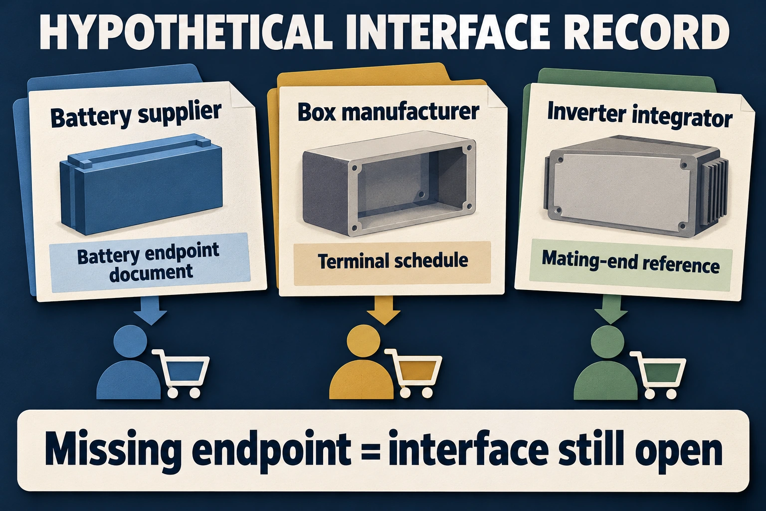
Consider a hypothetical order against system drawing D4. Battery supplier B1 owns the battery-side terminal definition; box supplier P1 owns the internal terminal schedule; cable assembler C1 owns the external lead; inverter integrator I1 owns the inverter-side endpoint. These are fictional parties and document identifiers, not an actual RITOKS project. The drawing names one external power-cable boundary and a separate communication harness. Neither is specified by the color of a cable shown in a quotation photograph.
P1's quotation Q2 includes the internal terminals but excludes the inverter lead. I1's scope sheet expects that lead to arrive with the box. The filled exception reads: external inverter lead, delivery owner unresolved, technical interface awaiting endpoint agreement. This is a commercial conflict even if every internal component listed by P1 is individually suitable. Adding “complete protection box” to Q2 would not identify who orders or manufactures the missing lead. The buyer should resolve that delivery boundary before comparing the proposal's apparent completeness with a competing quotation.
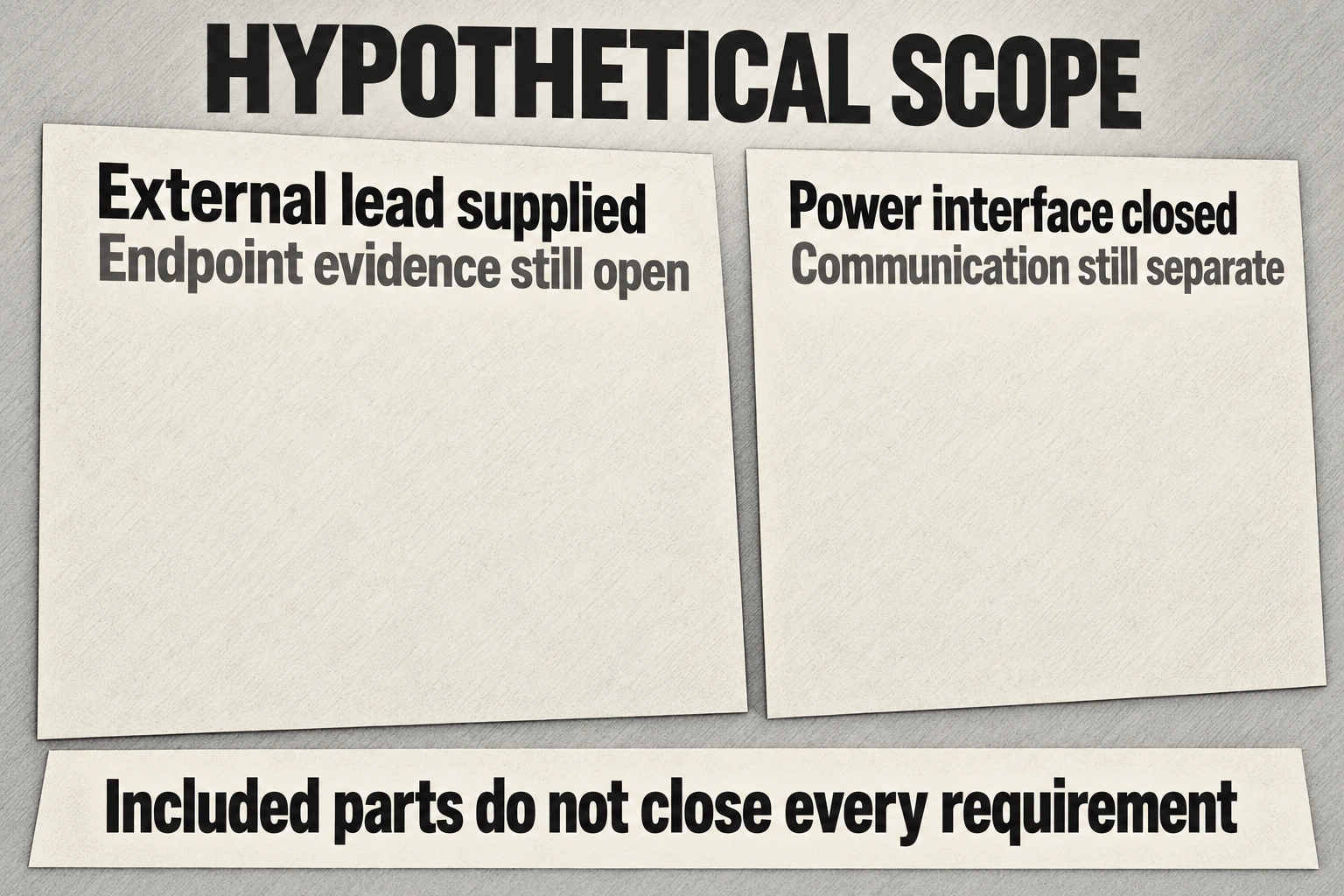
Suppose revised schedule Q3 assigns the external lead to C1 and both contracting parties accept that allocation. Commercial inclusion is now resolved: the lead is deliberately supplied outside the box order. Its technical status remains open because C1 has received P1's terminal schedule T2 but not I1's mating-end drawing. The purchasing decision can preserve the agreed commercial scope while holding cable fabrication. Asking P1 to include the lead again would reopen a settled ownership question without supplying the missing endpoint evidence.
I1 later supplies drawing E3 with the named endpoint and reference view. C1's assembly drawing A2 matches that interface and T2, and the responsible designer accepts the documented arrangement for D4. The interface field can now be closed for that exact lead proposal. Length and routing still follow the controlled assembly and layout records; this fictional example gives no terminal assignment, cable dimension or installation procedure. A later change from E3 to E4 requires review of the affected cable end rather than automatic reuse of A2 because the connector photograph looks similar.
The communication row has a different outcome. B1 identifies a supported protocol but I1 has not confirmed the equipment-version combination or harness scope. The power-lead decision does not close this row. Record its owners as B1 and I1, the missing evidence as the equipment/harness agreement, and the consequence as an unresolved system-integration task. P1 can supply a mechanically complete box without having accepted responsibility for that communication decision. Conversely, placing a communication socket on the enclosure does not prove that the two controllers will communicate.
Function ownership should remain equally explicit. Assume fictional equipment requirement R2 calls for a pre-charge function, while P1's quoted component list contains no documented pre-charge provision. If B1 later confirms that its equipment provides the required function within D4's agreed boundary, P1 need not duplicate it merely to make the box look more comprehensive. That conditional preference depends on R2 and B1's accepted scope, not on an inferred capability of TPBAT4-B7. If the equipment revision moves that responsibility outside B1's delivery, reopen the function row and identify its new owner before accepting the revised system.
The final record therefore distinguishes the external lead's accepted delivery owner and interface, the still-open communication combination, and the conditionally allocated pre-charge responsibility. A supplier reply is credited only to the question it answers. A statement about available fuse detection, for example, would not close the required fault-interruption row. This creates a practical stopping point: unresolved system integration can hold the applicable release even though preliminary enclosure pricing or a documented cable proposal is useful. The buyer does not need to pretend that all progress is lost, or that all progress is approval.
Retain D4, Q3, T2, E3, A2 and R2 with the accepted scope and open exceptions. All responses and dispositions in this example are invented to demonstrate the method; no compatibility, delivered function or measured result is claimed. When the battery, inverter or box changes, compare the revision with the interfaces it actually affects. A mechanical enclosure revision may leave the accepted lead unchanged, while a terminal or control revision can reopen a previously closed row. That targeted change review is more informative than an undifferentiated confirmation that the whole box is suitable.
المراجع
- Victron Energy. (n.d.-a). Lynx Distributor M8 and M10: Installation, sections 6.1–6.3. Manufacturer manual.
- Victron Energy. (n.d.-b). Lynx Distributor M8 and M10: Features, sections 3.1–3.3. Manufacturer manual.
- RITOKS. (n.d.). TPBAT4-B7 four-way battery protection box. نطاق المنتج.