
إدارة الحرارة · شرح تقني
Rack Fan Tray Thermostats: Verify Sensor Location and Start Threshold
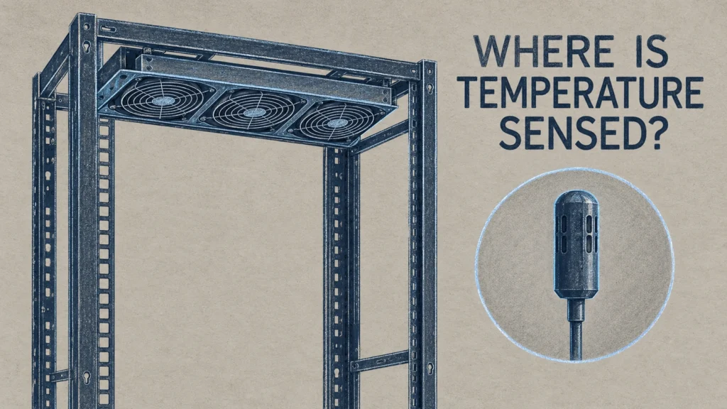
Quick answer
A thermostat-controlled rack fan tray responds to the temperature at its sensing element, not automatically to the hottest device in the rack. Confirm where that element is located, which temperature starts the fans, which condition stops them and how the actual equipment inlet temperature behaves during the same period. A fan starting correctly does not by itself prove that every device receives acceptable cooling.
Use the exact tray documentation and a location-labelled temperature record for acceptance. Do not copy a threshold from another fan tray, assume that a fixed thermostat is adjustable or treat the start temperature as an equipment temperature limit. This guide focuses on the complete tray's sensing and response, rather than the separate question of selecting a normally open or normally closed contact.
Identify the temperature that actually controls the fans
Start with the ordered assembly identity. A family name or suffix placeholder may cover different physical versions. Obtain the relevant drawing or instructions showing the thermostat or sensor position and whether the sensing element is integral to the tray or connected remotely. If the documentation does not identify it, request clarification instead of labelling a guessed position on the acceptance sheet.
Mark that position on the rack layout. Also identify the equipment inlet locations that the project needs to assess. The control sensor and equipment inlet are different measurement tasks, even if both are described informally as rack temperature. Keeping separate labels prevents an exhaust-area reading from being presented as the temperature of incoming air.
A manufacturer's control architecture illustrates why those distinctions matter. STEGO's DCT010 documentation separately lists an external sensor, adjustable temperature and switching differential. These are properties of that specified controller, not automatic features of a rack tray or evidence that its sensor can be moved (STEGO, n.d.).
For an integral sensor, document its installed relationship to the air path without modifying it. Moving a sensing element or altering a control circuit is not an acceptance shortcut. If its location does not represent the required control region, the designer needs to review the suitability of the assembly rather than redefining the meaning of its reading.
Keep start, stop and tolerance as separate fields
The start threshold states the condition at which the controller calls for fan operation. The stop threshold or switching differential describes the return condition. Tolerance and response characteristics explain how closely the physical response can be compared with the documented value. They are not interchangeable numbers on a thermostat dial.
Altelix's published NHBS-RACK-ER1U-F product page provides separate fan-on and fan-off temperatures with separate tolerances for its specified tray. It demonstrates why both transitions belong in the documentation review. Those values are not transferred here to an unspecified RITOKS orderable configuration (Altelix, n.d.).
Determine whether the supplied unit has a fixed threshold or an adjustment, and record the documented setting convention. A labelled adjustment is not necessarily a direct measurement of current air temperature. Likewise, a display value and the control sensor may need their relationship established by the instructions before they are used as the same acceptance evidence.
| Control field | Evidence to record | Interpretation to avoid |
|---|---|---|
| Exact assembly | Order code, nameplate and document revision | Treating every family suffix as an identical controller |
| Sensor position | Actual drawing or manufacturer clarification | Assuming it measures the hottest equipment |
| Start condition | Published fan-on rule and any setting | Calling it a universal equipment temperature limit |
| Return condition | Stop threshold or documented differential | Assuming the fan stops at the start value |
| Tolerance and response | Applicable controller specification | Treating any small observed difference as a failure |
| Adjustment scope | Fixed or adjustable control and permitted method | Assuming the user can reset a fixed thermostat |
Use blank or pending fields when documents are missing. Filling them with a value from a visually similar tray makes the record look complete but removes the distinction between a verified specification and an assumption. Procurement should resolve those gaps before an acceptance test depends on them.

Plan a location-labelled observation record
Define the acceptance question before collecting temperatures. One question is whether the fans respond according to the documented control rule. A separate question is whether the selected rack cooling arrangement supports the equipment's specified input conditions. The same log may help answer both, but it needs the relevant locations and fan-state observations.
Record the rack configuration, equipment operating case, room conditions and time basis with the log. Note the tray position, its intended airflow direction and any relevant path restrictions. This makes the observation traceable if a later change to equipment or rack hardware produces a different response.
Use suitable instruments and an approved commissioning procedure managed by the responsible personnel. This article does not prescribe heating energized equipment, blocking vents or defeating protection to force a thermostat transition. If the required observation cannot be obtained safely in normal or approved test conditions, document that limitation and request an appropriate manufacturer-supported method.
Include both the control region and the relevant equipment inlets where measurement is permitted. A single unlabelled maximum in a spreadsheet cannot show which location reached it or whether the fan had started. Maintain time alignment between readings and fan-state observations so the reviewer can distinguish a control response from an unrelated change in the environment.
| Observation record | What it should identify | Question it helps answer |
|---|---|---|
| Control-region temperature | Sensor relationship and instrument position | What local condition accompanied the response? |
| Equipment inlet temperature | Exact device and inlet location | Did the inlet remain within its documented requirement? |
| Fan state | Observed operation with the same time basis | Was the response associated with the control condition? |
| Operating case | Equipment configuration and load basis | What conditions does the record represent? |
| Installed path | Tray position, airflow direction and restrictions | Does the observed arrangement match the proposed installation? |
| Exceptions | Missing transitions, uncertain locations or unavailable documents | Which conclusions remain unverified? |
The table is a project record structure, not a mandated sampling interval or instrument accuracy. Select those requirements for the actual commissioning task. Keep original observations available instead of retaining only a pass label, particularly where a transition was not observed during the recorded period.

Assess response and equipment conditions independently
First compare the observed control response with the exact documentation, using its tolerance and permitted test method. If the response appears inconsistent, confirm the assembly and measurement relationship before diagnosing the thermostat. A nearby probe may not be at the sensing element, so an apparent threshold difference needs interpretation rather than an automatic component-failure conclusion.
Then review the equipment inlet conditions against the equipment documentation. A correctly operating thermostat can still be part of a cooling arrangement that is unsuitable for the rack layout. Fan operation proves that the tray is responding; it does not establish an installed airflow quantity or show that another device's inlet is protected.
Do not turn the difference between two locations into a permanent correction factor without supporting evidence. The relationship may change when the equipment operating case or air path changes. Use the measured relationship for the conditions recorded and identify the cases that remain outside that evidence.
Distinguish an acceptance failure from an incomplete test. If the fans did not cycle during an otherwise useful observation period, the log may support inlet-condition assessment but not verify both control transitions. State that limitation directly. A complete record can legitimately contain a pending item instead of stretching one observation into every required conclusion.
Specify the evidence needed with the tray order
الـ RITOKS NHBS-RACK-ER1U-Fx thermostat-controlled rack fan tray family describes a rack tray with thermostat-controlled fans and requires exact configuration confirmation. Its published page does not establish a particular sensor position, switching threshold, airflow or noise value for every orderable version.
Request the assembly drawing, control instructions, fan-on and return conditions, tolerances and supply information with the quotation. Send the intended rack position and equipment layout so the proposed version can be reviewed in context. Do not describe the family as providing a guaranteed inlet temperature merely because it includes a thermostat.
If the supplier proposes a substitute, compare its sensor arrangement and control rule as well as its physical fit. Matching rack height and fan count does not establish equivalent temperature control. Keep the accepted documentation with the final order code so a later replacement is not selected only from the appearance of the tray.
A conditional acceptance example
In a hypothetical rack project, the fans start during an approved observation period, but the log contains only a probe near the tray and no labelled equipment inlet readings. The team initially calls the rack cooling accepted because the thermostat operated. The reviewer separates the two questions and finds that the equipment-condition evidence is missing.
The team obtains the exact control documentation and completes the location-labelled record under an approved commissioning procedure. If the fan response matches the documented rule and the required inlet cases are supported, the arrangement can proceed through project acceptance. If inlet conditions are unsuitable despite correct fan response, the designer reviews the cooling layout rather than treating a lower guessed thermostat setting as an approved remedy.
This is a document-review example, not a reported performance test. It assumes neither adjustable control nor a numerical threshold, and it does not prescribe an unsafe way to create a temperature rise.
الأسئلة الشائعة
Does the tray thermostat monitor the hottest device?
Not automatically. Its sensing element responds at its own location. Establish that location and assess the relevant equipment inlets separately; neither the family name nor fan operation proves a rack-wide maximum temperature.
Can I use another manufacturer's threshold for acceptance?
No. A published value for another specified tray is useful context, not evidence for the ordered assembly. Use the exact version's documentation, including return condition and tolerance.
Is a running fan enough to accept rack cooling?
No. It supports an observation about fan operation. Equipment inlet suitability requires its own documented conditions and location-labelled evidence for the relevant operating cases.
What if the fans never stop during the observation?
Record the observed conditions and the unverified transition. Check the documented control rule through an approved procedure rather than inventing a pass or forcing unsafe conditions. An incomplete transition check is different from a demonstrated fault.
المراجع
Altelix. (n.d.). Rack mount fan tray with four thermostat-controlled cooling fans. https://altelix.com/altelix-rack-mount-fan-tray-with-four-thermostat-controlled-cooling-fans/
STEGO. (n.d.). DCT010 electronic thermostat. https://www.stego-group.com/en-gb/products/dct-010