
Current Shunts for DC Measurement Systems · Technical Explainer
DC Shunt Heating: Estimating Loss Without Assuming a Safe Temperature

Quick answer
A shunt's millivolt output is small, but the associated power loss need not be negligible. Multiplying current by the voltage drop gives a useful estimate of heat generated in the resistive element. It does not tell the designer the operating temperature, whether the surrounding installation can remove that heat or whether the selected model's conditions are satisfied.
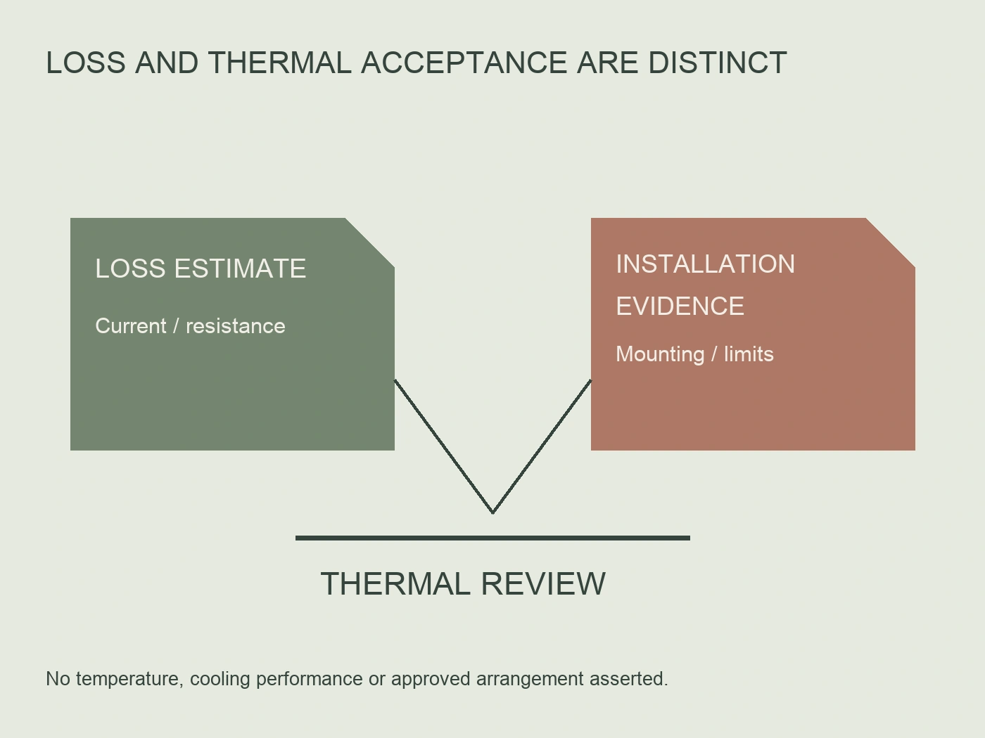
DC current shunt power dissipation and heating should therefore be reviewed in two stages: estimate electrical loss using the applicable resistance and current, then assess temperature against exact-model limits and actual installation conditions. Keep the calculation, thermal evidence and acceptance decision separate. A watt figure alone is not a temperature guarantee. Where the shunt sits in the circuit is a separate question; see low-side vs high-side shunt measurement.
This guide is for DC distribution and thermal-design reviews. It provides an arithmetic example and a record for requesting the missing installation evidence, not a loading test or live-temperature measurement procedure. Physical testing and installation work require the manufacturer's instructions and the project's authorized arrangements.
Define the voltage drop used in the calculation
For a resistive element under the stated conditions, use P = I × V and, with V = I × R, P = I² × R. Here I is current through the element, V is its corresponding voltage drop and R is the resistance used for the estimate. Identify the values and their conditions before using the result in a thermal review.
Tento RITOKS FL-2-75 DC shunt family is a 75 mV output family with multiple current variants. Use the selected variant's current and corresponding output declaration, not the family's highest current alongside a different model's information. A common output designation does not make every variant dissipate the same power at its own rated current.
The manufacturer's sensing connection definition also matters. A voltage measured across an installation's current-carrying connections may include losses beyond the intended resistive element. Do not treat an unexplained terminal-to-terminal measurement as a clean shunt-element calculation. Request the applicable sensing points and installation documentation before interpreting the result.
Texas Instruments' shunt selection brief SBAA460 separates resistance and dissipation requirements from temperature limits, mounting and derating assessment. Its discussion covers several construction types. Use the principle, not its illustrative mounting assumptions or fractional-current guidance, as the basis for requesting FL-2-specific evidence.
Work through a clearly hypothetical example
Consider a hypothetical shunt specified to produce 75 mV at 100 A. This is an arithmetic teaching example, not a selected FL-2 orderable model, a test result or an approved operating point. Assuming constant resistance for the calculation, the implied resistance is 0.075 V ÷ 100 A = 0.00075 Ω.
At 100 A, the element-loss estimate is 100 A × 0.075 V = 7.5 W. At 50 A with the same assumed resistance, its voltage drop is 0.0375 V and the estimate is 50 A × 0.0375 V = 1.875 W. Halving current reduces this fixed-resistance loss to one quarter; it does not prove a particular temperature reduction.
| Hypothetical calculation | Aktuální | Assumed resistance | Corresponding drop | Estimated element loss |
|---|---|---|---|---|
| First operating point | 100 A | 0.00075 Ω | 75 mV | 7.5 W |
| Second operating point | 50 A | 0.00075 Ω | 37.5 mV | 1.875 W |
The table deliberately contains no temperature column. Temperature cannot be supplied from these electrical values alone. Nor does the lower-loss row establish a permissible continuous duty, ambient condition or load profile. Those are separate model and installation questions.
If resistance changes with temperature, the fixed-resistance assumption needs review. Retain its source and reference conditions rather than presenting the estimate as exact over all operating temperatures. Any refined calculation should identify the manufacturer's applicable resistance-versus-temperature information and the method used by the designer.

Distinguish generated heat from the resulting temperature
The loss calculation describes heat generation. Its removal depends on the selected construction and installation. A chassis shunt connected into a conductor arrangement should not be assigned a surface-mount resistor's PCB heat path or a generic thermal resistance from an unrelated component.
Ask for the manufacturer's allowable temperature conditions, relevant measurement locations and derating information. Confirm how these relate to the proposed ambient conditions, mounting and conductor connections. If the supplier's limits refer to a terminal temperature, do not substitute an enclosure-air reading or a reading from another point without an applicable basis.
Retain the enclosure and cooling configuration in the thermal review. A calculation made for one mounting arrangement does not automatically remain valid after a change to the current connections, nearby heat sources or ventilation. Record what the assessment actually represents so that a later assembly change can be recognized.
Where the required thermal data are unavailable, describe the gap. “Estimated loss known; permitted temperature not established” is a useful conclusion. It is more precise than approving the shunt because the watt figure appears small, or declaring it unsuitable because no temperature estimate has been produced.
Keep connection losses outside the element estimate
The resistive element is not the only possible source of heat in a current path. TI's brief cautions that chassis-shunt primary connection installation can add resistance and affect losses. This supports a separate connection review; it does not provide an FL-2 fastening value, approved conductor size or predicted contact loss.
Request the selected model's connection instructions and retain the relevant installation specification. Do not invent a universal torque or assume that an apparently tight connection has the documented resistance and thermal behavior. Any installation inspection or remedial work belongs to the authorized electrical-work process.
In the engineering record, state whether the estimate covers only the element or includes documented additional losses. Avoid expanding a single calculated watt value into a complete assembly heat budget without identifying the other inputs. Conversely, do not attribute an unexpected localized temperature to the element solely because the shunt is nearby.
This boundary is especially useful during an investigation. A reviewer can ask whether the measured location, connections and current condition correspond to the original assessment. The answer should come from the controlled inspection and test evidence, not from changing the loss formula until it matches a desired explanation.
Evaluate thermal effects on measurement separately
Temperature is relevant to the measurement result as well as to thermal acceptance. Request the selected shunt's resistance temperature coefficient and its applicable range. Keep that information distinct from initial tolerance and from the performance of the connected meter or receiving circuit.
TI's current-sensing technical article discusses the trade-off between shunt resistance, dissipation and measurement performance in its amplifier-selection context. That supports reviewing the signal chain rather than treating reduced resistance as a free improvement. Its amplifier examples are not compatibility or accuracy claims for the RITOKS family.
For a project requiring an error estimate, have the responsible engineer identify the relevant coefficient, operating-temperature evidence and measurement-chain assumptions. This article does not supply a coefficient or derive a guaranteed error. A calibration performed under one condition is not automatic evidence of the same result at another temperature.
If someone proposes a lower-output or different-current shunt to reduce loss, review the meter input and scaling as a separate changed requirement. The present task is thermal assessment, not approval of a replacement measurement chain. Record both decisions so that an attractive thermal change does not silently invalidate the intended reading.
Build a loss-and-temperature correspondence record
Use the following original worksheet to connect the calculation with the evidence needed for acceptance. It is a review aid, not a completed thermal report or product rating table. Each row should identify its document or responsible reviewer rather than merely show a checkmark.
| Recenzovaný produkt | Důkazy, které je třeba uchovat | Decision boundary |
|---|---|---|
| Electrical estimate | Exact variant, current condition, resistance or corresponding drop | What element loss was estimated? |
| Thermal limits | Manufacturer temperature and derating documents | Which location and conditions do the limits cover? |
| Instalace | Mounting, connections and cooling configuration | Does the assessed arrangement match the assembly? |
| Povinnost | Continuous and other relevant operating conditions | Which cases have actually been reviewed? |
| Measurement effect | Applicable coefficient and chain assessment | What accuracy conclusion is supported? |
| Acceptance | Controlled calculation or test findings and named reviewer | What remains unresolved or conditional? |
For example, the electrical estimate is complete, but only a general ambient-temperature statement has been supplied. Leave temperature acceptance unresolved until the relevant shunt conditions are clarified. Do not convert that statement into an invented maximum element temperature.
In another case, a documented thermal assessment exists but the current-connection arrangement changes during assembly. Preserve the earlier result, identify the changed input and request review of the affected finding. Reusing an old temperature result without its mounting conditions would obscure the reason it was accepted.
Continuous-loss arithmetic also does not establish short-term overload capability. Request the manufacturer's applicable duty and overload information where those cases matter. No deliberate overload or fault test is proposed here. A defined project test should be performed only under its authorized plan and documented limits.
Compare a filled element record with an incomplete installation record
Extend the earlier hypothetical constant-resistance case, not an actual FL-2 measurement. Record E1 contains the assumed element resistance of three quarters of a milliohm and its one hundred ampere operating condition, giving the previously calculated seven and a half watts. Record J1 adds a fictional aggregate connection resistance of one tenth of a milliohm in the same current path. This additional resistance is an invented teaching input, not an expected contact value, permitted allowance or tightening result. Its purpose is to keep element and connection contributions distinguishable.
At one hundred amperes, that assumed aggregate connection term contributes one watt through current squared times resistance. The identified subtotal becomes eight and a half watts: seven and a half in the element plus one in the defined connection term. It is not the complete cabinet heat budget; other components have not been included. If the current becomes fifty amperes with both resistances held constant, the connection term becomes one quarter watt and the subtotal becomes two point one two five watts. The earlier element-only result of one point eight seven five watts is still correct within its narrower boundary.
Suppose fictional installation document T1 supplies only enclosure ambient conditions and no applicable selected-shunt temperature or derating basis. E1 and J1 now make heat generation more explicit, but T1 still cannot turn either subtotal into a safe element or terminal temperature. The filled decision is “loss inputs identified; thermal acceptance unresolved.” Adding connection watts is useful scope correction, not a thermal simulation. The result must not become a claim that the lower-current condition is an approved continuous rating.
Now assume a responsible engineer supplies assessment T2 for an identified mounting and conductor arrangement A1, with selected-model limits and the corresponding temperature evidence. That document can support its stated acceptance only within A1's assessed scope. If the panel proposal changes the conductor attachment or nearby cooling arrangement to A2, E1's electrical calculation may remain a useful input while T2's installation conclusion requires review. The decision reverses because the heat-removal basis changed, not because the calculation suddenly ceased to be arithmetic.
An alternative shunt proposal adds another independent question. A lower-loss element might be attractive, but its output and current definition must remain compatible with the receiving measurement chain. The thermal reviewer cannot approve that chain merely by comparing watts, and the measurement reviewer cannot approve temperature merely by matching millivolts. Preserve the original accepted arrangement while requesting the alternative's two affected assessments. All records and outcomes here are hypothetical; no measured contact resistance, field temperature, exact-model mounting result or actual product substitution is claimed.
Close the review with model-specific evidence
Send the supplier the exact variant, intended current conditions and proposed installation information. Ask for the corresponding voltage-drop basis, mounting instructions, temperature limits, derating data and applicable temperature coefficient. Identify any duty or overload case that needs separate assessment.
The final record should say both what generates heat and why the resulting temperature is acceptable for the reviewed arrangement. If that second conclusion is not yet supported, retain the loss estimate as useful information and keep acceptance pending. The practical distinction is simple: calculated watts describe loss; temperature and measurement suitability require their own evidence.
Literatura
- Texas Instruments. (n.d.). Shunt selection technical brief SBAA460. https://www.ti.com/document-viewer/lit/html/SBAA460
- Texas Instruments. (n.d.). Current-sensing technical article SSZTCI1. https://www.ti.com/document-viewer/lit/html/SSZTCI1/GUID-E4077072-44EB-4162-8D61-477A4178AC03
- RITOKS. (n.d.). FL-2-75 Odbočky pro stejnosměrný proud. https://ritoks.com/products/fl2-75-dc-current-shunts-10a-5000a/