
Hall Effect Current Sensors for Isolated Measurement · Selection Guide
Hall Current Sensor Selection Guide: Range, Output and Fit
A practical selection guide covering current waveform, operating range, output compatibility, supply and conductor fit.
Quick answer: select a complete measurement chain
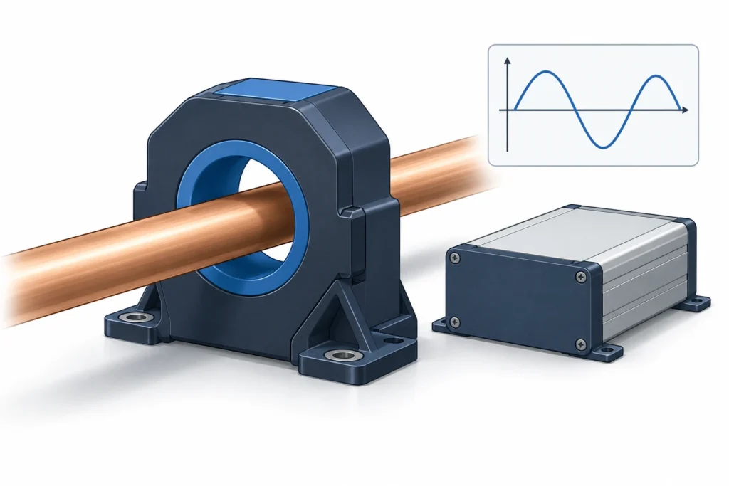
Select a Hall current sensor by checking six things together: the current waveform, normal and peak current, usable output range, available supply, conductor fit, and the required measurement accuracy. A current rating alone cannot establish compatibility. The selected sensor must measure the required operating envelope, and the receiving equipment must accept the resulting signal without clipping or losing useful resolution.
Begin with the measurement objective. Recording average battery current, displaying a load value and capturing a short transient are different jobs. Write down what the equipment must report, how often it must report it, and the smallest change that matters to the application. Those requirements make it possible to compare models on useful performance rather than choosing the largest current number in a catalogue.
This guide provides a purchasing and engineering review sequence, not instructions for working on energized equipment. It includes a hypothetical comparison to show how the same current requirement can lead to different interface decisions. Actual installation, insulation coordination and protection functions require the exact equipment documentation and a qualified system designer.
1. Describe the current before selecting the sensor
Record whether current is DC, AC, pulsed or a combination, and whether its direction can reverse. Describe the measurement location as well as the machine. For example, a DC supply feeding an inverter does not make every conductor in that system a DC measurement point. A diagram identifying the intended conductor is more useful than the label “inverter application.”
LEM's Hall technology overview describes open-loop and closed-loop approaches for DC, AC and complex waveforms. This establishes a technology-level capability, not approval of any particular model for every waveform. The exact sensor's frequency response and operating limits still determine its suitability.
For a fluctuating load, supply a current trace if one exists. Otherwise, distinguish normal operation, startup and exceptional events in the inquiry. Include the duration of each event. A peak value without a timescale leaves the supplier unable to judge whether the requirement is continuous measurement, transient capture or merely survival of an abnormal condition.
Also state whether the reading is intended for monitoring, control or protection. A sensor selected for a display is not automatically qualified to perform a safety-related shutdown. Keep that requirement visible from the beginning rather than discovering it after the electrical interface has already been designed.
2. Separate nominal current, measuring range and overload
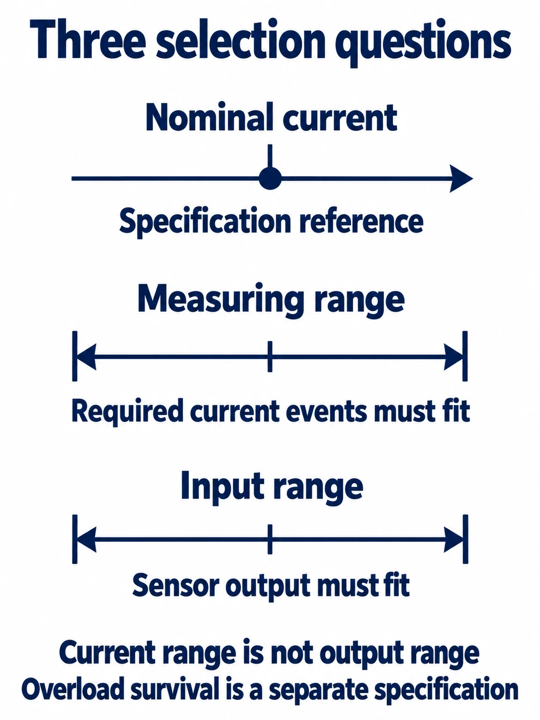
Treat these as separate fields in a comparison sheet. Nominal current is the reference point used in the model's specifications. Measuring range describes the current interval stated for measurement. An overload or absolute maximum rating, when provided, is a separate limit and must not be treated as a guaranteed usable measurement interval.
For the HS2V H02 family offered by RITOKS, the manufacturer's electrical table lists a 400 A nominal model with a ±1200 A measuring range and an 800 A nominal model with a ±2400 A range. The nominal reference and measuring limits are therefore not interchangeable. These values come from the exact-family Chinese V5 data sheet, page 3, not from a neighbouring current-transformer catalogue.
A useful shortlist has two separate questions. First, does the documented measurement envelope cover the required current events? Second, will ordinary readings occupy enough of the receiving instrument's range to be useful? Passing the first question does not answer the second. A very large range can cover a peak yet leave the normal signal unnecessarily small.
Do not apply an automatic oversizing percentage to every application. Instead, state which uncertainty needs margin: future load growth, an incompletely characterized startup event or variation among machines. A named uncertainty can be discussed with the supplier. An unexplained margin can conceal a poor match between the normal operating current and the required reading quality.
3. Match the output to the receiving equipment
Read the complete input specification of the PLC, acquisition module or meter. “Analog input” is not a sufficient description. Record its accepted voltage or current range, input type, loading requirements and reference arrangement. Identify the exact module and channel configuration; equipment from the same manufacturer may have different input options.
The HS2V H02 data sheet specifies a ±15 V supply and approximately ±4 V analog output at nominal current, with its electrical table stated at 25°C and a 10 kΩ load unless otherwise noted. The output-at-nominal entry is a reference point, not a statement that every current in the measuring range produces an output confined to ±4 V. Supply voltage and output voltage are different requirements.
Build an output-envelope question into the review. What signal will the receiving input see at the smallest important current, normal current and maximum required event? Ask for the documented transfer relationship and applicable limits. Do not infer a full output envelope from a single headline value, and do not assume a software scaling setting can correct an electrically incompatible input.
Keep polarity distinct from input topology. A channel that can represent positive and negative values is not necessarily a differential input. Conversely, having two input terminals does not establish permission to accept any negative voltage relative to its reference. The module's documentation, not the terminal count or software display, decides that question.
If signal conditioning is required, include it in the comparison rather than treating it as a later accessory. Its input limits, output range and effect on the measurement must be evaluated as part of the chain. A sensor with an attractive nominal specification can still be the wrong purchasing choice when the required interface adaptation is not practical.
4. Choose architecture against the measurement objective
Open-loop and closed-loop Hall sensing should be compared using the requirements already recorded. LEM explains that closed-loop designs use compensation and can offer advantages in accuracy, response and temperature stability, while open-loop designs can favour simplicity and lower supply consumption. These are general tradeoffs; compare exact products rather than assigning a guaranteed performance level to either label.
For a slow trend display, the useful question may be whether the error is acceptable throughout the ordinary current interval. For a control measurement, response and the usable waveform information may matter more. For an application that must distinguish small bidirectional currents around zero, request the offset behaviour as well as the nominal-current accuracy.
Make each architecture decision traceable to one requirement. “Closed loop because the specification is better” is incomplete. “Candidate rejected because its documented response does not meet our event-capture requirement” is actionable. The same method also prevents assuming that an open-loop model is unsuitable merely because a different technology has a stronger headline figure.
5. Evaluate error where the reading matters
Ask how each accuracy figure is defined. A percentage of nominal current, a percentage of reading and an offset expressed as output voltage do not describe the same thing. Write the basis next to the number. If offset is excluded from a quoted accuracy value, do not present that value as the total error of the installed system.
For example, the HS2V H02 table states accuracy of ±1% of nominal current at nominal current, excluding electrical offset. That wording does not establish ±1% of reading throughout the full range. A buyer concerned with small currents needs an assessment at those small currents, not a claim extrapolated from the nominal operating point.
Set an acceptance target in the units the user needs. If a display must distinguish two nearby operating states, specify their current separation and the conditions under which the distinction must remain reliable. The engineer can then evaluate the sensor, input module and scaling together. This is more informative than requesting “high precision” without defining the decision the reading supports.
Calibration should also have a defined purpose. Ask whether the system needs a zero adjustment, a span adjustment or traceable verification at particular operating points. Do not promise that a single adjustment eliminates every source of error. Record which conditions will be assessed and which remain outside the acceptance test.
6. Check the conductor and installation envelope
Compare the dimensioned sensor drawing with the actual conductor assembly. Include insulation, cable lugs, bends, adjacent conductors, mounting access and any enclosure constraints. A bare busbar measurement is not necessarily the installed envelope. A conductor that fits through an opening may still be difficult to route or secure in the intended cabinet.
For a retrofit, establish whether the conductor can be disconnected during an authorized outage. Do not assume an aperture-style sensor can be installed like a split-core device. The purchasing request should state the installation constraint before a model is chosen, especially where downtime determines whether a candidate is practical.
Keep mechanical fit separate from insulation suitability. Physical separation does not by itself establish an acceptable working voltage or installation category. Request the exact-model insulation information and let the system designer assess it against the intended equipment. Likewise, a standards reference on a data sheet is not automatically a product certificate or a certificate covering the complete assembly.
7. Worked example: why two ranges need different reviews
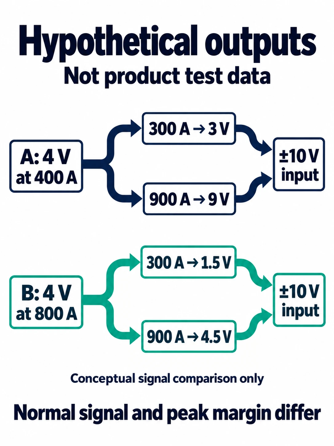
The following example is hypothetical, not a RITOKS test result. A machine normally operates at 300 A, reverses current direction, and has an event reaching 900 A that the operator wants to record. Its available acquisition channel accepts −10 V to +10 V. Two fictional sensors have ideal linear responses and zero offset: Candidate A produces 4 V at 400 A, while Candidate B produces 4 V at 800 A. For this example only, assume both sensors have documented linear operation through 900 A and that all other compatibility requirements remain unresolved.
Using the assumed relationship, output equals 4 V multiplied by current divided by nominal current. Candidate A therefore produces 3 V at 300 A and 9 V at 900 A. Candidate B produces 1.5 V and 4.5 V respectively. Reversing the assumed current reverses the ideal output sign. These are arithmetic results of the stated assumptions, not predictions for an actual HS2V device.
| Hypothetical candidate | Output at 300 A | Output at 900 A | Question still requiring evidence |
|---|---|---|---|
| A: 4 V at 400 A | 3 V | 9 V | Does the real worst-case output remain within the input's usable limits? |
| B: 4 V at 800 A | 1.5 V | 4.5 V | Can the complete chain distinguish the smallest important current change? |
Candidate A uses more of the assumed input range during normal operation, but its peak signal leaves less room before the input limit. Candidate B has a smaller peak signal, but that alone does not prove better overall measurement. Neither can be selected from the ideal calculation alone. Supply tolerance, offset, real transfer limits and the input's performance must be included before the shortlist becomes an approved design.
The example shows why the range and interface reviews belong together. Choosing a sensor first and asking about the input afterward can force a second purchase or an unnecessary conditioning stage. Conversely, rejecting the smaller nominal rating simply because it is below the peak ignores the separate measuring-range specification. Document both sides of the chain before deciding.
8. Send an RFQ that can produce a usable answer
Prepare one requirement record for the measurement point. Include the waveform and direction, normal operating interval, peaks and their duration, the smallest useful change, and whether the purpose is monitoring, control or protection. Attach the conductor drawing and the receiving module specification. State the available supply and the equipment environment rather than asking the supplier to guess them.
Ask the supplier to return the exact proposed model, current-envelope assessment, output relationship, input compatibility assumptions and any unresolved requirements. Request supporting documentation for claims that determine acceptance. If the reply supplies only a model number and price, the technical selection is still incomplete even when the quotation is commercially attractive.
Použijte RITOKS Hall current sensor category to identify the relevant product family, then send the requirement record to sales1@ritoks.com. An inquiry should distinguish confirmed requirements from estimates so that the proposed model can be reviewed against the same information used by your engineering team.
Final selection record
Before ordering, record why the chosen model meets the application and why the alternatives were not selected. Keep the exact data-sheet revision, receiving input configuration and relevant drawings with that record. If the conductor arrangement, input module or required peak changes later, review the affected selection questions rather than assuming the original approval still applies.
A defensible selection is not the sensor with the most impressive isolated number. It is the model whose documented measurement capability, interface and installation requirements fit the job, with remaining uncertainties made explicit. That approach also makes supplier discussions faster: each open question has a specific owner and a clear document or assessment that can close it.
Literatura
- LEM: Hall Effect Current Sensors. Technology-level principles only; not evidence of RITOKS model performance.
- CHIPSENSE. (2025). HS2V H02 Series Chinese V5 data sheet, document reference 1800 000 01085, printed date 12/17/2025. Accessed October 7, 2026 through the manufacturer's current product page. Exact-family electrical data on page 3; confirm the applicable revision before procurement.