
Technische Ressourcen · Technische Erläuterungen
Panel Meters in Industrial Switchboards: Application Inputs
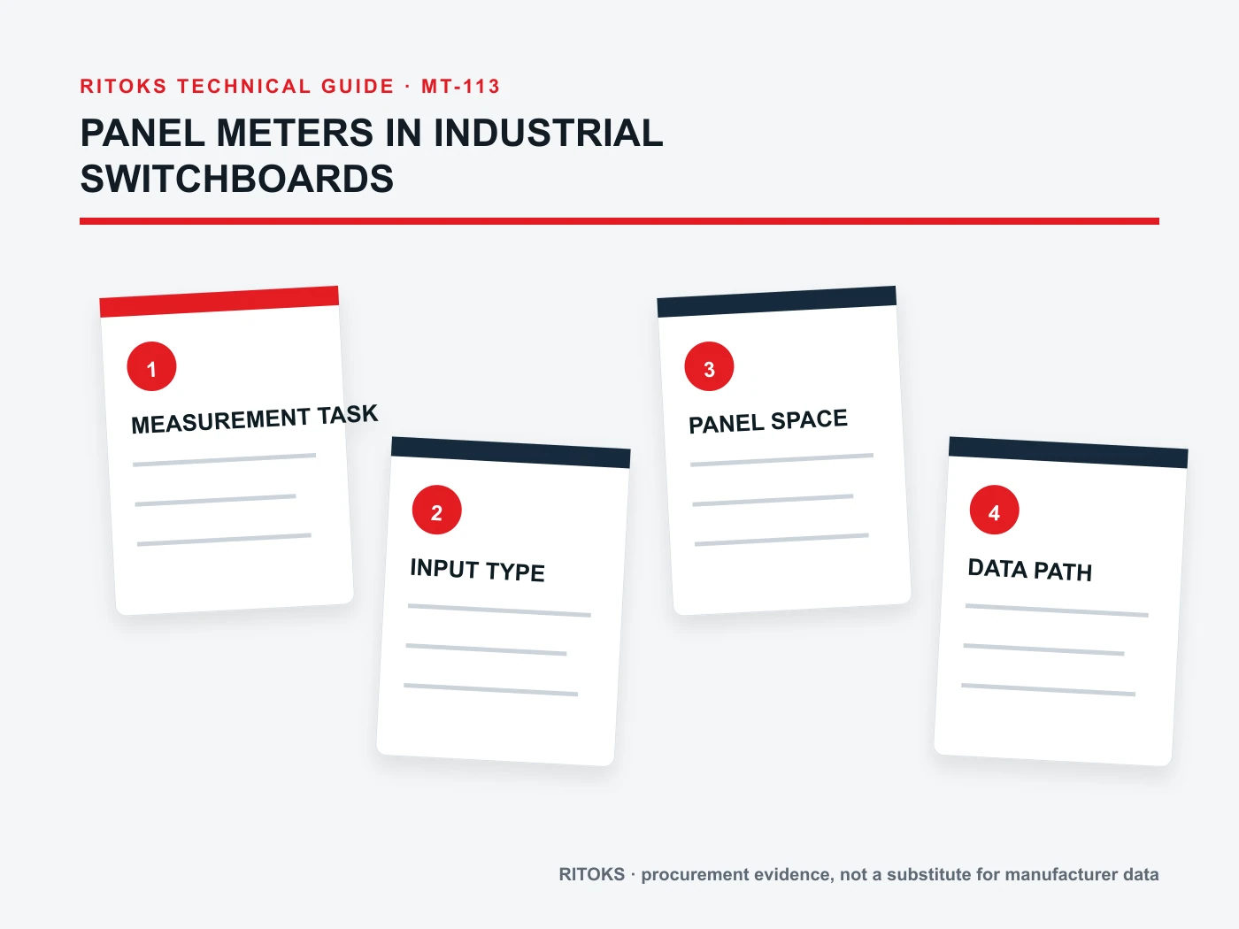
Panel meters in industrial switchboards serve different users: an operator checking local voltage, a maintenance technician tracing phase current, an energy manager reviewing consumption and a control system collecting values remotely. The right display depends on those tasks, the electrical measurement path and the available panel space, not simply on the number of digits on the bezel.
This application guide shows how to define measurement, visibility and communications before selecting a meter family. It does not claim that a particular RITOKS model meets an unverified switchboard specification. Exact input, accuracy, mounting and protocol evidence remains necessary.
Identify the decision the measurement supports
Start with the question the user must answer. Is the value needed only for a quick local operating check, an alarm, troubleshooting, energy allocation or remote trend analysis? A simple voltage indicator may be sufficient for a local check, while power or energy reporting may need a multifunction meter with transformer inputs and communications.
List all quantities and how often they are needed. Voltage, current, frequency, power factor, active power and energy are different functions. Determine whether the operator must see several values at once or can select and scroll through pages. Avoid specifying a multifunction device merely because it has more features; unused complexity can make daily interpretation harder.
Identify whether values are for control decisions or only indication. A display that helps a technician diagnose a circuit is not automatically suitable as a protective relay or safety interlock input. If the value feeds automation, define update rate, communication quality and response to missing data separately.
Map the switchboard electrical system
Document the board's single-line, nominal and maximum voltages, phase arrangement, frequency and measured feeder location. Identify whether the meter will connect directly to voltage and current or through CTs and VTs. A switchboard may contain circuits with different conductor and grounding arrangements, so a generic “three-phase meter” request can be incomplete.
For CT-operated measurement, provide CT ratio, secondary output and polarity orientation. The meter hardware must be compatible with that secondary. Ratio programming does not solve a current-output versus voltage-output mismatch. A direct-connected device has different installation and current limits; do not treat the two architectures as equivalent because both display amperes.
Record where auxiliary power comes from and whether it remains present when the measured feeder is de-energized. That detail can affect alarm and communications availability. Ask for the exact meter's input and supply wiring diagram before the switchboard drawing is frozen.
Plan visibility from the operator's position
A front-panel meter is an interface, not just a sensor. Consider reading distance, viewing angle, lighting, units, label space and how frequently the operator checks the value. A small LED voltage display can work as a status indicator in one board, while a larger multifunction interface may be needed for detailed local diagnostics.
Define which values must be visible without navigation. If a meter cycles automatically, ensure the displayed quantity is identifiable. An unlabelled number can be misread during maintenance. Keep the panel engraving and meter configuration consistent; if the board is exported to multiple markets, consider whether units and symbols remain clear.
Ask how alarms appear and what they mean. A colored display segment or alarm contact should not be interpreted as a safety system unless the overall design establishes that role. If operators need to acknowledge or reset events, specify that workflow before choosing a model.
Decide what remote communication must deliver
Remote monitoring begins with a list of required values, not a port label. State whether the supervisory system needs real-time readings, energy totals, alarms or historical data. Define physical network, protocol, addressing and register documentation. “RS-485” describes an interface but not the complete data contract.
Check how many devices share the network, who sets addresses and what happens after a meter replacement. A communication-capable meter may expose a different register map or scale than an existing model. Coordinate with the PLC or energy-management team before the panel bill of materials is approved.
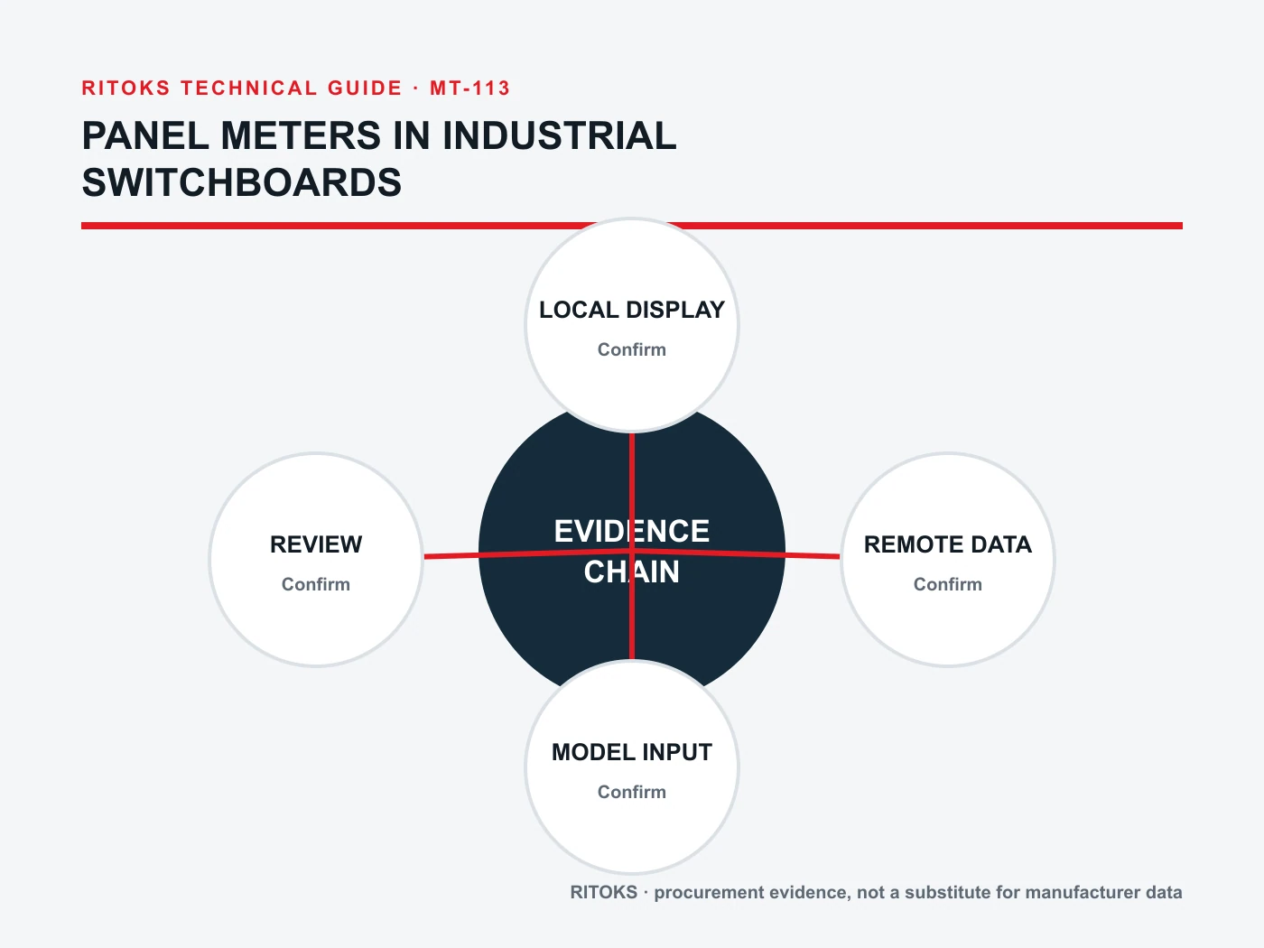
Schneider Electric's energy-meter manuals show that wiring type and CT/VT ratio are configured as part of the measurement system. That is an example of why commissioning settings matter; it is not a claim about RITOKS meter menus or protocols. Ask for the exact candidate's user manual and register documentation.
Match measurement quality to the use case
Accuracy should be specified for the quantity and operating range that matter. A display may resolve small changes but still have a larger measurement error. If the system uses CTs or VTs, their ratio, class, wiring and burden affect the overall measurement chain. The meter's standalone accuracy does not describe the complete installed system.
For energy allocation or commercial reporting, state the required evidence and verification procedure. For a local maintenance indicator, a different performance target may be appropriate. Do not add a billing claim to a general-purpose panel meter without current certification and application evidence.
Define a commissioning check: compare readings with a known reference at a suitable operating point, verify phase assignment, CT polarity and configured ratios, and record the result. Values that look plausible can still be scaled incorrectly by a wrong transformer setting.
Fit the meter to the physical board
Provide panel cutout dimensions, door thickness, rear depth, terminal access and available cable routing. A front-bezel size is not the cutout. Retrofit projects should include the existing hole and a photograph with scale; the new meter may need an adapter or a panel change.
Consider the enclosure's environment. Front-panel sealing, temperature range and mechanical mounting should be checked against the exact installation instructions. A meter fitted into a poorly prepared cutout can compromise door sealing, even if the device itself has a published front protection rating.
Coordinate the display layout with other controls. Grouping meters by feeder or function can make the board more readable. Labels should identify source and quantity without needing a separate drawing for routine operation. The physical arrangement does not alter electrical accuracy, but it affects human interpretation and maintenance time.
Application matrix for selection
| Switchboard task | Likely input question | Anzufordernde Nachweise |
|---|---|---|
| Local voltage check | AC/DC, range and phase point | Exact input and display data |
| Feeder current | Direct or CT-operated path | Current input and ratio setup |
| Power/energy review | System wiring and CT/VT scheme | Function and accuracy documents |
| Remote monitoring | Protocol and data list | Interface and register map |
| Retrofit | Cutout and supply available | Dimension and installation drawing |
The matrix is a conversation starter, not an automatic product selector. Several tasks can coexist in one board, but adding all functions to one meter may not be the best operational arrangement. Determine which displays must remain visible if communications fail and which data can be remote-only.
Consider service life and replacement
A switchboard may remain in service long after the original meter is discontinued. Keep the cutout drawing, terminal diagram, transformer ratios and communication register map with the board records. A replacement should be checked for both physical fit and interpretation of data. The same display value can be scaled or labelled differently if the new instrument uses another setup method.
Where meters feed remote reports, identify how data continuity is preserved during replacement. A new meter may reset energy totals or use a different register offset; the supervisory system needs an explicit cutover plan. For a local-only indicator, check whether the operator still sees the same critical quantity without extra navigation. These considerations belong at selection time because they affect which functions are worth specifying.
RITOKS options and an actionable inquiry
Die digital panel meters category is the commercial entry point. The D85 AC voltage/current family, multifunction power meter family und AD16-22 voltage display family address different likely tasks. Their family pages do not prove the detailed input or communication specification of a selected variant.
Send the one-line drawing, required quantities, input method, CT/VT details, display task, cutout, supply and remote data requirements via RITOKS-Kontakt. Request exact-model manuals and ask the supplier to identify any mismatch. A well-scoped inquiry makes the choice between a local indicator and a networked meter straightforward to evaluate.
Common application questions
Does a multifunction meter replace all local indicators?
Not automatically. Consider what must remain visible at a glance, the operator workflow and the consequences of a shared device or display failure.
Can an RS-485 meter be installed without a data plan?
It may operate locally, but remote integration needs protocol, addressing, register map and commissioning ownership. The interface alone does not define useful data.
Why verify CT ratio during commissioning?
An incorrect ratio can scale otherwise plausible readings. Check hardware compatibility, wiring and meter setup together against the actual CT.
Fazit
Choose a switchboard panel meter from the measurement decision, electrical input path and user interface. Then confirm fit, accuracy and remote data on the exact model. A bright display is valuable only when it shows the right quantity from the right circuit to the right user.