
Disyuntores miniatura de corriente continua (MCB) · Guía técnica explicativa
DC MCB Installation Location in PV and Battery Systems
Map DC MCB positions in PV and battery systems and the voltage, fault-current, direction and enclosure checks each position needs before selection.
Quick answer
Place a DC MCB where it protects a defined conductor or device against a defined fault source. In a PV array, that usually means string or sub-array positions in a combiner box only when the number of parallel strings creates a reverse-current or overload risk; with one or two strings, reverse-current protection is normally not needed. In a battery system, the breaker sits close to the battery output, a DC distribution branch or a converter feed, because the battery can deliver high fault current in either direction. Each location needs its own voltage, current, fault level and pole wiring check against the exact breaker datasheet.
Location is the first design decision because it fixes everything that follows. The same 2P DC MCB can be correct at a 48 V battery branch and wrong at a 1000 V PV string input, even if the current rating looks the same. Buyers who send a breaker request without saying where the device will sit can receive a quotation that answers the wrong question.
This guide maps the common positions in PV and battery systems, explains what each position asks of the breaker, and lists the drawing information a supplier needs before confirming a model. It is a design-input guide. It does not replace the installation standard that applies to your project or the protection study of a qualified designer.
Why location changes the breaker requirement
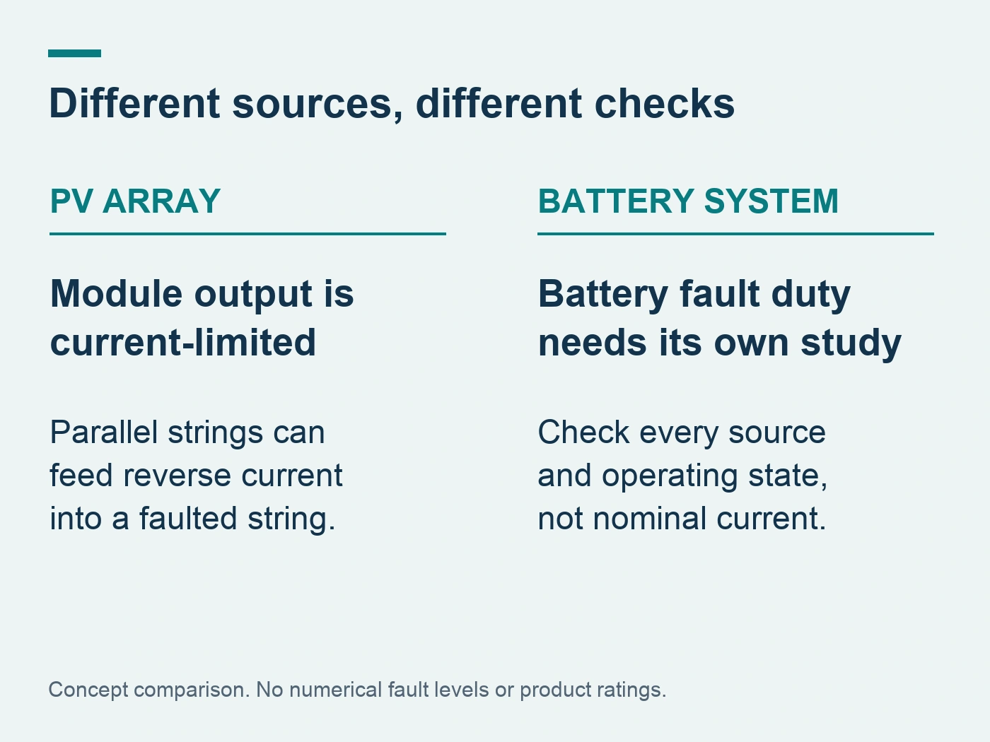
A circuit breaker is selected for a circuit, not for a system. Moving it from one point to another changes four things at once.
The first is voltage. A PV string input sees the string's maximum open-circuit voltage at the lowest expected cell temperature. A battery branch sees the battery's maximum charge voltage. A converter output may see a regulated bus voltage. These values can differ by several hundred volts in the same installation.
The second is prospective fault current. PV modules are current-limited sources: the Schneider Electric Electrical Installation Guide notes that the short-circuit current produced by a PV module is too low to trigger the automatic disconnection of the supply. A battery is the opposite case. Its fault current is limited mainly by internal resistance and cabling, so a branch close to a battery can see a much higher fault level than any point in the PV array.
The third is current direction. In a PV string, reverse current flows from healthy parallel strings into a faulted string. In a battery system, current reverses between charging and discharging as part of normal operation. A direction-sensitive breaker that is acceptable at one point may be unsuitable at another. Our guide to polarized vs non-polarized DC MCBs covers that evidence in detail.
The fourth is what the breaker is actually protecting. A string breaker protects modules and string cables against reverse current and overload. A battery branch breaker protects the branch conductor and the equipment it feeds. A main battery breaker may also be expected to serve as an isolation point for maintenance. Each function has different evidence requirements.
Positions in a PV array
String position in a combiner box
String overcurrent protection is only needed when enough parallel strings exist to drive a dangerous reverse current into one faulted string. The Electrical Installation Guide gives the condition as:
1.35 × I_RM < (N_s − 1) × I_SC_MAX
Here I_RM is the module's maximum reverse current from the module manufacturer, N_s is the number of parallel strings, and I_SC_MAX is the maximum string short-circuit current. The same source states that with one string there is no reverse-current risk, and with two identical strings the reverse current always stays below the module limit, so string protection is not needed in those cases.
A hypothetical example shows how quickly the answer changes. Assume a module datasheet lists I_RM = 20 A and the string I_SC_MAX is 11 A. The left side is 1.35 × 20 = 27 A. With three strings, the right side is 2 × 11 = 22 A, so the condition is not met. With four strings, it becomes 3 × 11 = 33 A, which exceeds 27 A, and string protection is required. These numbers are illustrative only; use the actual module datasheet and the edition of the installation rules adopted for your project.
Where string protection is required, the guide cites IEC 60364-7-712:2017 clause 712.433.1.101.2: the protective device rating should be greater than 1.5 times and below 2.4 times the module short-circuit current I_SC_MOD. For an I_SC_MOD of 10 A, the rating must be above 15 A and below 24 A. IEC lists the 2017 edition as withdrawn on 2025-10-21 and replaced by IEC 60364-7-712:2025, so confirm the current clause in the edition your designer uses before freezing ratings.
Sub-array and array position
When strings are grouped into sub-arrays, each sub-array cable can be protected at the array box. The same guide gives the sub-array device rating as greater than 1.25 times and below 2.4 times the sub-array short-circuit current at standard test conditions (clause 712.433.1.101.3 of the 2017 edition; check the corresponding clause of the 2025 edition adopted for your project). The guide also notes that circuit breakers allow closer adjustment than fuses at this level, which can help where sub-array cables are smaller.
Voltage and pole arrangement at array positions
Array positions see the full open-circuit voltage of the string. The Electrical Installation Guide states that breakers and switches in PV systems are designed to break current with all poles in series at U_OC_MAX, and gives the example that breaking at 1000 V requires four poles in series, two per polarity. A 2P breaker described as 1000 V DC must therefore show exactly how its poles are wired to reach that rating. Ask for the manufacturer connection diagram before accepting it. See 2-pole vs 4-pole DC circuit breakers for how pole architecture affects selection.
Inverter DC input
At the inverter input, the main need is often isolation for maintenance rather than overcurrent protection. The Electrical Installation Guide notes that fuses do not provide a load-break function, so an array box with string fuses should also have a main switch. Whether a breaker or a separate DC isolator serves this point depends on the function required. Our Seccionador de CC frente a disyuntor de CC guide explains the difference.
Positions in a battery system
Battery output and string position
The breaker nearest the battery has the highest fault duty in the system. The datasheet must show a DC breaking capacity at a voltage at least equal to the battery's maximum voltage, with the stated pole wiring. A rated current that matches the battery's continuous output does not show that the device can interrupt the battery's prospective short-circuit current. The designer should obtain the fault current from the battery manufacturer or a calculation, then compare it with the breaker's documented capacity. Our guide on DC MCBs in battery circuits lists those inputs.
Battery positions also carry bidirectional current in normal service: charging in one direction and discharging in the other. A fault can be fed from the battery side, from a charger side, or from both. Confirm whether the candidate breaker is polarized, and if it is, whether its marked orientation remains valid for every source that can feed a fault at this point.
DC distribution branches
Branch breakers downstream of a battery bus protect individual cables and loads. Their fault level is lower than at the battery terminals, but it is still set by the battery and the upstream cable, so it must be calculated rather than assumed. The branch breaker's rating must protect the branch cable, so the cable size, installation method and ambient temperature belong in the request. Breaker curves must also coordinate with cable limits; see DC cable protection studies.
Low-voltage battery systems in vehicles, RVs and telecom cabinets often need high branch currents at modest voltage. RITOKS lists the RTS-DC250-125 high-current DC MCB for DC 12–125 V with 63–250 A in 1P or 2P, which suits that position only after the system voltage, fault current and conductor size are confirmed.
Converter and charger connections
A DC breaker between a battery bus and a converter can see capacitor charging current when the converter is connected. This inrush can be large for a short time. The breaker's instantaneous trip characteristic should be checked against the converter manufacturer's inrush data so that normal switching does not cause tripping. If the converter can back-feed the bus, treat the point as a two-source location.
Location map at a glance
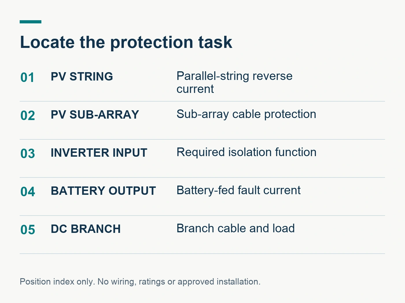
| Puesto | Main protection task | Voltage to check | Fault source to check | Typical evidence to request |
|---|---|---|---|---|
| PV string (combiner) | Reverse current and string cable overload, only when the string count requires it | String U_OC_MAX at lowest temperature | Parallel healthy strings | Rating window per adopted installation rules; pole wiring diagram |
| PV sub-array | Sub-array cable protection | Array U_OC_MAX | Other sub-arrays | Rating window; DC breaking capacity at stated pole wiring |
| Inverter DC input | Isolation, sometimes protection | Array U_OC_MAX | Array and inverter | Load-break or isolation function; utilisation data |
| Battery output | Short-circuit and overload of main battery cable | Battery maximum voltage | Battery, plus chargers that can back-feed | DC breaking capacity at battery voltage; polarity statement |
| DC branch | Branch cable and load protection | Bus voltage | Battery bus via upstream cable | Trip curve vs cable limits; ambient derating |
| Converter feed | Cable protection without inrush trips | Bus voltage | Battery bus and converter back-feed | Instantaneous trip data vs inrush; direction statement |
The table is a starting map. Real projects add earthing arrangements, surge protection, monitoring devices and local code requirements that can change the position or type of device.
Enclosure and environment at the chosen location
Location also decides the thermal environment. PV combiner and array boxes are usually outdoors. The Electrical Installation Guide warns that high ambient temperatures and high IP enclosures can reduce air flow and heat dissipation, and that wiring poles in series for high voltage increases device temperature. A breaker that runs comfortably at 30 °C on an open rail may need derating inside a sealed outdoor box in summer. Our article on MCB ambient temperature and grouping derating explains what to request.
The same guide states that Part 7-712 of IEC 60364 calls for DC-side enclosures to meet IEC 61439 assembly requirements. Separately, the guide recommends that DC-side enclosures provide double insulation. Where switchgear is rated for pollution degree 2 rather than 3 in a 1000 V system, it gives a minimum enclosure protection of IP5x. These are enclosure decisions, but they affect which breaker can be installed and how it is rated.
What to put on the drawing before asking for a quote
A supplier can only confirm a breaker for a position it can see. A useful request includes:
- A single-line diagram marking every proposed breaker position, with each source that can feed a fault.
- The maximum voltage at each position, stating whether it is PV open-circuit voltage at minimum temperature or battery maximum charge voltage.
- The prospective fault current at each battery-connected position, with its source.
- The continuous current and the cable size, installation method and ambient temperature for each protected conductor.
- The earthing arrangement of the DC system, because it changes how faults involve each pole.
- Whether the position must also act as a maintenance isolation point.
- Quantity per position and destination market, so the applicable standard can be matched.
With that information, the quotation can name a specific configuration and its documented limits instead of a generic family. Our Lista de comprobación para solicitar un presupuesto de MCB de CC gives the full list of commercial and technical fields.
Common location mistakes
Three errors appear repeatedly in DC protection requests.
Adding string breakers to every string by default. When only one string, or two identical strings, exist, the reverse-current condition cannot be met, and extra devices add cost, heat and connection points without a protection benefit. Check the inequality first.
Using a PV-rated breaker at a battery position because both are "DC". The PV breaker's documented breaking capacity may be well below a battery's fault level, and its polarity marking may not suit a bidirectional circuit.
Reading the 1000 V figure without the wiring diagram. High DC voltage ratings on MCBs often depend on a specific series connection of poles. If the panel builder wires the device differently, the documented rating may no longer apply.
Buyer questions
Can one DC MCB model serve every position in a hybrid PV and battery system?
Only if its documentation covers the highest voltage, highest fault current and every current direction across those positions. In practice, the battery positions and the PV array positions usually need different configurations or families.
Does a DC MCB at the battery replace a battery fuse?
That is a design decision for the system designer and the battery manufacturer. Some battery manufacturers specify a particular protective device at the battery terminals. Follow that requirement; a breaker is acceptable only if the designer confirms it meets the specified duty. Our DC fuse vs DC circuit breaker guide compares the two approaches.
Which RITOKS product fits a PV string position?
El RTS-DC63-1000 2P DC MCB has a supplier-listed 500–1000 V DC scope with 6–63 A ratings, and the RTS-DC63-500 covers DC 500 V systems. The exact model is confirmed after we receive the string voltage, short-circuit current and required wiring arrangement. You can compare the family on the DC miniature circuit breakers category page.
Finish with a position-by-position list
Treat each breaker as an answer to one position: what it protects, which sources can feed a fault there, what voltage it must break, and which way current can flow. Put those answers on the single-line diagram before choosing a model. A request built this way gets a precise quotation and avoids discovering mismatches during commissioning.
Referencias
- Schneider Electric. (2026). PV System: how to ensure safety during normal operation. Electrical Installation Guide. Retrieved October 23, 2026, from https://www.electrical-installation.org/enwiki/PV_System:_how_to_ensure_safety_during_normal_operation
- International Electrotechnical Commission. (2017). IEC 60364-7-712:2017 Low-voltage electrical installations – Part 7-712: Requirements for special installations or locations – Solar photovoltaic (PV) power supply systems [Withdrawn 2025-10-21]. Retrieved October 23, 2026, from https://webstore.iec.ch/en/publication/28213
- RITOKS. (n.d.). High-current DC miniature circuit breaker, 12–125V, 63–250A. Retrieved October 23, 2026, from https://ritoks.com/products/high-current-dc-miniature-circuit-breaker-12-125v-63-250a/