
Disipadores térmicos para módulos de potencia · Guía técnica
Several Power Modules on One Heatsink: Account for Thermal Coupling
Quick answer
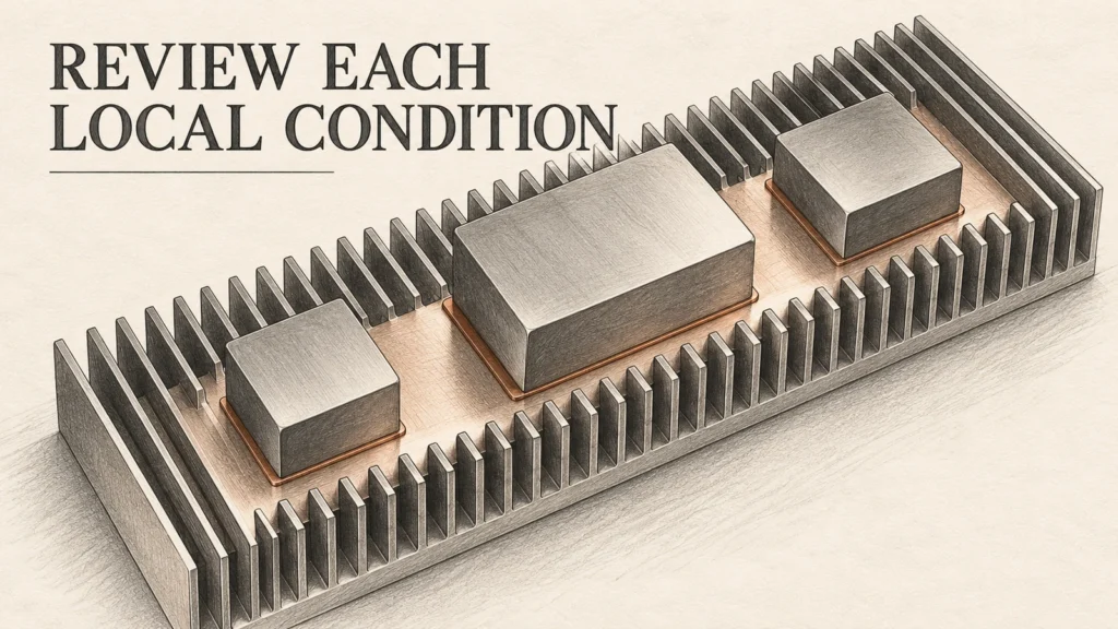
A shared heatsink must remove the losses of all operating modules while keeping each module within its own documented thermal limits. Do not divide a single-source heatsink resistance by the number of modules and assume that every mounting position has the same temperature. The source locations, loss distribution, interface and cooling arrangement determine whether that approximation represents the assembly.
Build a module-position and loss map, then obtain thermal evidence for the proposed multi-source layout. Evaluate the hottest relevant local condition rather than relying only on an average heatsink temperature. This guide provides a review record for that decision; it does not assign a cooling capacity to an untested heatsink or prescribe a spacing rule for every power module.
Separate total heat removal from local temperature
Total dissipation tells the cooling system how much heat must leave the assembly. It does not identify the temperature below a particular module. Two arrangements can have the same total loss but different positions, mounting footprints or cooling exposure. A layout that concentrates the losses in one region therefore requires its own evidence, even when the total matches a previously reviewed arrangement.
Thermal coupling describes the interaction when nearby heat sources share heat-flow space. Semikron Danfoss explains this interaction in its discussion of semiconductor packaging and thermal modelling, including why the operating combination and available heat-spreading area matter. The examples concern specified semiconductor structures; their numerical distances are not general clearance rules for separate modules on a cabinet heatsink (Semikron Danfoss, 2025).
Keep the temperature quantities distinct. A heatsink measurement is not a junction measurement, and a baseplate or case measurement is not automatically the hottest semiconductor temperature. The selected module documentation must establish how the relevant quantities are used in its thermal assessment. Replacing them with a convenient surface reading can conceal an unexamined part of the heat-flow path.
For a purchasing review, the practical question is not whether coupling exists in the abstract. It is whether the offered evidence describes the proposed module count, positions and operating losses well enough to support the required limits. If a curve represents one centred heat source, label it that way. Do not silently present it as a multi-module temperature map.
Build a position and loss map before comparing heatsinks
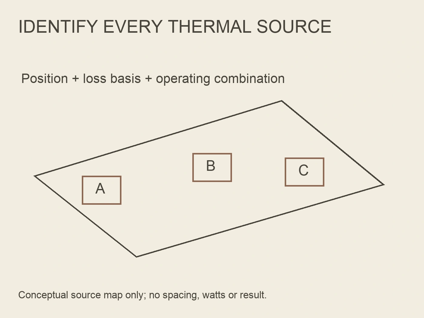
Give each module a stable identifier and place it on a dimensioned mounting drawing. Record its footprint, orientation and relationship to the other sources. Include the cooling direction where relevant, because a forced-air arrangement is more than a heatsink profile plus a fan catalogue entry. The actual cabinet path and restrictions belong in the evidence package.
Use losses established for the intended operating cases, not the module's current rating as a substitute for watts. If losses are estimated, state the calculation basis and remaining uncertainties. Different modules may contribute different losses, and their maximum contributions may or may not occur together. The designer must identify the combination the cooling assessment needs to cover.
| Map field | Record for every relevant source | What the reviewer can decide |
|---|---|---|
| Identidad del módulo | Exact module and documentation revision | Which thermal limits and interfaces apply |
| Mounting position | Footprint, orientation and coordinates | Whether the submitted thermal layout matches the assembly |
| Loss basis | Operating case, calculation or measurement source | Whether heat inputs represent the intended duty |
| Concurrent operation | Which sources operate together | Whether a single-source assessment misses shared loading |
| Interfaz | Specified material and mounting requirements | Whether the contact condition matches the evidence |
| Cooling environment | Local air conditions, orientation and installed path | Whether the heatsink data apply to the proposed installation |
Keep maximum and normal cases separate on the record. A normal operating temperature can help explain the assembly but cannot replace the required limiting case. Equally, summing unrelated maxima without explaining whether they can occur together can create a misleading specification. Record the assumption instead of burying it in an unexplained total.
Where a source moves or a model changes, revise the map before reusing the thermal result. Similar outline dimensions do not prove equivalent loss, interface or allowable temperature. The map is the bridge between the electrical operating assumptions and the mechanical drawing, so both should identify the same assembly revision.
Ask what the thermal evidence actually represents
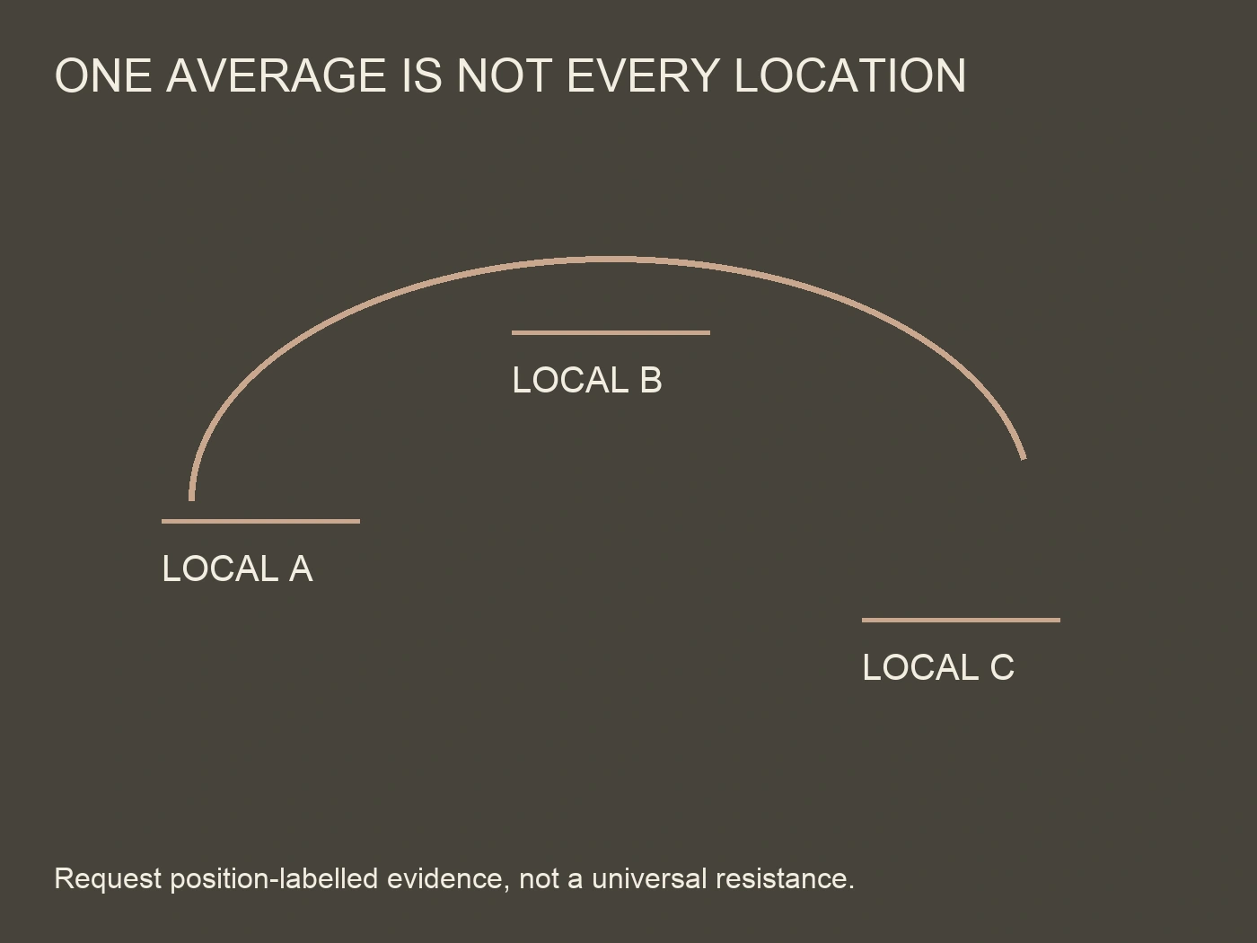
A useful supplier submission identifies the test or model arrangement, heat inputs, reference temperature and cooling conditions. Ask where the heatsink temperature was measured and whether the reported resistance is tied to that location. A single value without those details cannot show that every module on the proposed base has adequate thermal conditions.
Infineon's CIPOS Maxi application note separates the heat source-to-heatsink interface, heat transfer within the heatsink and heat transfer to ambient. It also discusses how source distribution, airflow and orientation affect heatsink behaviour. These principles explain why an installed arrangement needs review; its model-specific curves and mounting values are not specifications for another module or a RITOKS heatsink (Infineon Technologies, 2024).
Look for a temperature distribution or local measurement record rather than only an attractive thermal image. The record should identify positions, operating case and measurement method. An image without a scale or source map may show a warm region, but it cannot establish a documented temperature at the point required by the module assessment.
If simulation is used, request its boundary conditions and the basis for interface and cooling inputs. Ask how the result has been checked against the actual or representative assembly. A model can support layout decisions, but changing the fan path or mounting interface after the calculation changes the question it answers. Do not approve a different configuration merely because the software output looks detailed.
Review the interface and cooling path together
The shared base does not eliminate individual interfaces. Each module still needs the mounting surface and thermal interface required by its own instructions. Check whether the heatsink drawing and manufacturing information meet those requirements across every intended footprint, not only the original mounting location.
Infineon's installation manual for its specified solder-bond modules warns that contact-surface condition affects heat distribution and that unsuitable contact can lead to local overheating. That is a reason to request the applicable surface and interface requirements; the manual's numerical tolerances are restricted to its described modules and are not copied here as a universal machining requirement (Infineon Technologies, 2017).
For natural convection, establish the intended orientation and surrounding space from the relevant documentation. For forced air, identify the fan, airflow path and installed restrictions used in the thermal evidence. A free-air fan rating by itself does not describe flow through the assembled cooling path. Any operating case that the project requires with degraded cooling needs a separately defined assessment, not an assumed reserve capacity.
Do not solve a thermal problem by prescribing arbitrary changes to electrical spacing, busbars or mounting torque. Moving sources may affect connections and other design constraints. Thermal evidence can identify a layout issue, but the responsible design review must consider the whole assembly before the revised arrangement becomes the approved drawing.
Use a multi-source evidence request for procurement
RITOKS offers an aluminum passive power-module heatsink and an SF/XSF forced-air heatsink family. Their published pages describe different cooling approaches and require application-specific confirmation. Neither supplies a general thermal resistance or a guaranteed capacity for an arbitrary multi-module layout.
Send the position and loss map with the request rather than asking for a heatsink based only on module current or count. Identify which characteristics are fixed and which the supplier may propose. If the offered configuration changes, require the revised evidence to identify that configuration clearly.
| Prueba | Question to resolve | Incomplete response to avoid accepting |
|---|---|---|
| Source layout | Does the result cover the submitted footprints and positions? | A drawing for a single centred module |
| Loss combination | Which sources and duty cases generated the result? | A capacity label with no heat-input basis |
| Local temperatures | Where are the relevant mounting temperatures established? | One average or an unlabelled image |
| Interface conditions | Which contact and mounting requirements were used? | An unspecified generic interface allowance |
| Cooling conditions | Does the installation match the assessed orientation or air path? | A fan description without the installed arrangement |
| Revision identity | Can the evidence be tied to the delivered assembly? | A test report for an unidentified configuration |
A conditional layout-review example
In a hypothetical converter project, a supplier previously assessed one module on a heatsink. The buyer now proposes several modules, with the largest loss source near one end. The total loss estimate appears acceptable compared with the earlier proposal, but there is no evidence for the new mounting positions.
The reviewer does not divide the earlier resistance by the source count. Instead, the team submits the revised drawing and concurrent loss cases, requests local mounting-temperature evidence, and checks the interface and cooling assumptions. If the new evidence supports every module's documented thermal assessment, the layout can proceed through approval. If it shows an unacceptable local condition, the designer reviews a revised layout or cooling arrangement and updates the evidence.
This example is a document-review process, not a reported test result. It specifies neither a minimum spacing nor a guaranteed improvement from moving a module. Its purpose is to make the missing multi-source evidence visible before an earlier single-source result becomes an unsupported approval.
Preguntas frecuentes
Can a single heatsink resistance be divided by the module count?
Not without a model that justifies that operation for the actual layout and definition of resistance. Source position, concurrent losses and cooling conditions matter. A source-count shortcut does not establish each local module temperature.
Does equal module loss mean equal module temperature?
No such conclusion follows from the loss alone. The positions, interfaces and cooling exposure also need review. Use evidence for the proposed arrangement rather than assuming thermal symmetry from matching electrical modules.
Can a thermal camera image prove junction temperature is acceptable?
Not by itself. Identify what surface the image measures, its measurement limitations and how that quantity relates to the module's documented thermal assessment. A surface image is not automatically a measurement of an internal junction.
What should accompany a multi-module heatsink RFQ?
Send exact module identities, a dimensioned source layout, loss and duty cases, interface requirements and installed cooling conditions. Request evidence tied to the proposed assembly and local positions; do not ask the supplier to infer all of them from module count.
Referencias
Infineon Technologies. (2017, October 13). Use and installation manual: 34mm and 50mm solder bond modules (AN2018-07, Revision1.3). https://www.infineon.com/dgdl/Infineon-Use_and_Installation_Manual_34mm_and_50mm_Solder_Bond_Modules-ApplicationNotes-v01_03-EN.pdf?fileId=5546d462576f3475015775517f2622cd
Infineon Technologies. (2024, June3). CIPOS Maxi IPM: IM12BxxxC1 series application note (V1.00). https://www.infineon.com/dgdl/Infineon-CIPOS_Maxi_IPM_IM12BxxxC1_series-ApplicationNotes-v01_00-EN.pdf?fileId=8ac78c8c90530b3a01908868b8ec22fb
Semikron Danfoss. (2025). Application manual: Power semiconductors (3rd revised edition, AB509142199100en-000205, Sections3.2.3.4 and6.2). https://assets.danfoss.com/documents/latest/530447/AB509142199100en-000205.pdf