
Bridge Rectifier Modules · Technical Explainer
Six-Pulse SCR Bridges: Mapping Phase Order to the Firing Channels

Separate three numbering systems
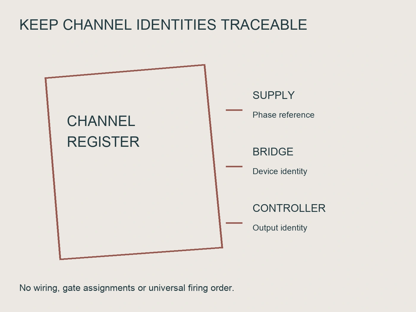
Keep supply-phase names, semiconductor identifiers and firing-board channel names in separate columns. Each has a different owner. The incoming supply drawing defines the phase reference; the bridge drawing defines which device occupies each circuit position; the controller documentation defines which output delivers a gate signal relative to its synchronization input.
ABB's DCS800 hardware manual illustrates why copying identifiers is unsafe. Its power-interface documentation uses device labels and gate/cathode connections specific to the depicted converter arrangement. Those labels belong to that ABB construction, not to every six-SCR bridge (ABB, n.d.-a). A controller channel called A elsewhere does not automatically correspond to the first device number on another manufacturer's drawing.
Le MTB38018F3FU-RF3 three-phase fully controlled SCR bridge page describes a six-SCR three-phase architecture and six gate-trigger connections. It explicitly requires order-specific documentation for the selected configuration. It does not publish a complete universal firing-channel assignment or authorize connection from the model name alone (RITOKS, n.d.).
Before accepting a drawing, check its order code, revision and applicable configuration. A family brochure might identify the architecture without defining every terminal. Keep a missing gate/cathode pin assignment as an open item, even when the power terminals appear obvious from the product photograph.
Establish the controller's synchronization reference
The firing controller needs a documented relationship to the AC supply. Record which inputs provide synchronization, how they are labeled and which phase sequence the controller supports. Include the reference-transformer or sensing arrangement where the controller manufacturer requires one. Do not assume a direct connection, neutral reference or sensing voltage from the bridge architecture.
Ask how the controller detects an invalid or missing reference and what happens to its gate outputs. Record the documented behavior rather than inventing a fail-safe response. A board with visible gate outputs may still lack the synchronization arrangement required for the selected bridge.
The commissioning record should distinguish the supply's phase identification from confirmation of the controller's interpretation. Matching cable labels does not prove that a synchronization transformer, connector or configuration parameter preserves the intended relationship. The responsible engineer should identify the approved checks that establish this relationship without improvising hazardous measurements.
| Interface | Document owner | Question to resolve |
|---|---|---|
| Incoming phases | System electrical drawing | Which actual conductors define the project phase reference? |
| Synchronization input | Firing-controller manufacturer | What reference connection and phase relationship are required? |
| Bridge device labels | Exact bridge circuit drawing | Which device is connected at each circuit position? |
| Gate and cathode terminals | Bridge terminal drawing | What is the defined signal connection for each device? |
| Isolated output channels | Firing-board documentation | Which output drives each documented device position? |
This table is an interface checklist, not a wiring schedule. Populate it with the supplied documents and their revisions before creating the actual connection schedule. Blank entries expose missing evidence; they should not be filled with a generic diagram downloaded for a different assembly.
Create a channel-to-device mapping record
Make one row for each controlled device in the actual bridge drawing. Retain the manufacturer device identifier, the firing-board output identifier, the gate terminal, its associated cathode reference and the supporting drawing reference. Include connector designations when they are defined. Do not rename everything into a simplified sequence and discard the original identifiers.
A reviewed mapping must answer two questions: whether each output reaches the intended device and whether its return/reference belongs to that same documented interface. Counting six wires or six output indicators does not answer either question. Similarly, a complete table does not prove that the physical assembly matches it until the approved verification has been performed.
Gate isolation must be assessed as part of the complete firing interface. Ask for the controller's channel isolation arrangement and the applicable operating conditions. Do not treat a small signal connector as an ordinary shared-ground control terminal unless the exact documentation establishes that connection. The power-circuit device positions may have different electrical potentials.
Where pulse transformers are used, preserve the primary-to-secondary channel relationship in the mapping. ABB's DCS800 service manual treats pulse presence on the primary side, pulse presence on the secondary side and transfer to the thyristor gate as distinct diagnostic questions (ABB, n.d.-b). That supports a layered evidence approach, not permission to copy ABB test methods onto an undocumented third-party assembly.
Keep waveform expectations tied to the actual design
Request the firing controller's description of pulse timing, pulse form and behavior over the supported operating range. The bridge supplier should supply the gate-interface requirements for the selected thyristors or assembly. Compare those documents rather than selecting pulse current, pulse width or repetition behavior from a general rule.
Do not publish a numbered firing sequence until the reference and numbering convention have been established. Two correct diagrams can use different device numbers for the same electrical positions. A sequence detached from its diagram is therefore ambiguous, even if it contains six numbers and looks familiar.
The mapping review should also identify which evidence would reveal a synchronization mismatch, a missing channel or an incorrect physical connection. These are different faults. An output-command log demonstrates controller activity; it does not alone prove that the gate received the intended signal or that the semiconductor conducted correctly.
When measured waveforms are required, the authorized procedure must define instrument isolation, connection points, operating condition and interpretation. This article deliberately provides no probe placement or test energization sequence. Record whether a waveform was actually witnessed, supplied by the manufacturer or only predicted by the design calculation.
Distinguish interface faults from power-circuit faults
Avoid attributing every unexpected output waveform to the firing order. The power circuit, supply and load also influence rectifier behavior. A mapping record should make those boundaries visible so that an investigation does not replace a bridge when the real problem lies in synchronization, a gate connection or the external circuit.
ABB's DCS800 service manual separates checks of the power section from the path between firing-pulse generation and the thyristor gate. It also identifies simultaneous line-voltage and current records across the supply phases as part of its own diagnostic context (ABB, n.d.-b). The general lesson is to retain correlated evidence; the specific ABB procedure remains limited to the equipment it covers.
For procurement, ask the assembly supplier which functions are included. A bridge with cooling hardware is not necessarily supplied with a firing controller, synchronization sensing or complete protection. The commercial scope should state these inclusions explicitly rather than letting the phrase “fully controlled bridge” imply a complete adjustable power supply.
L'actuel bridge rectifier module category is useful for identifying the relevant product family. It does not make the gate interfaces of its different rectifier architectures interchangeable. Keep uncontrolled diode bridges, semi-controlled bridges and fully controlled SCR bridges separate in the request.
Review the evidence before acceptance
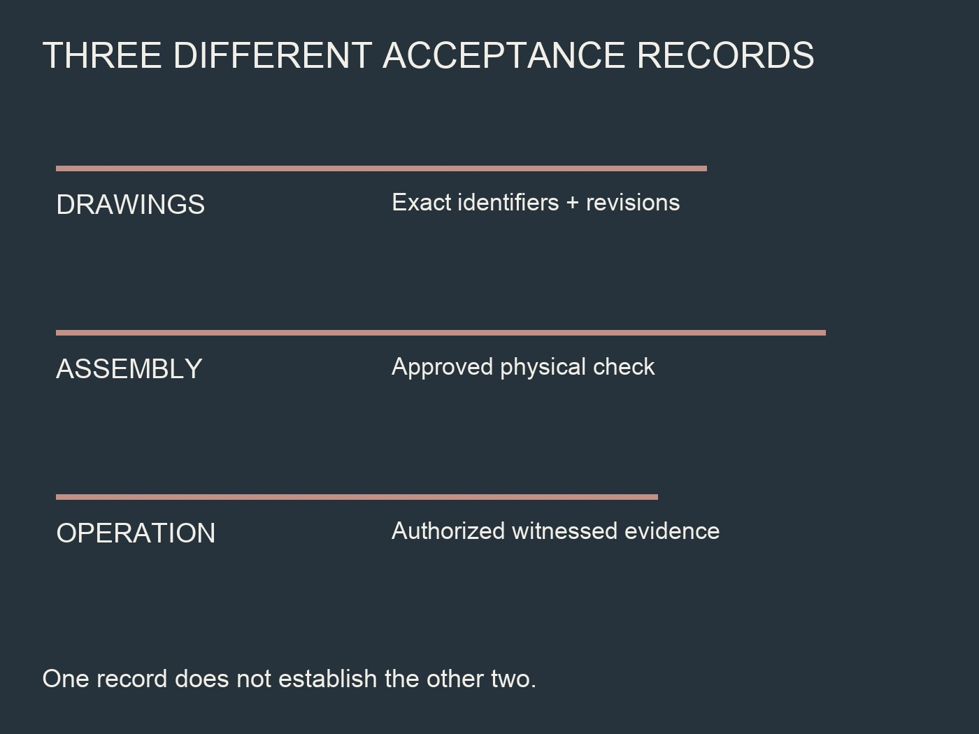
The acceptance package should allow a reviewer to trace every channel to a circuit position and every circuit position to a documented device. Record who prepared the mapping, which revisions were used and who approved it for the actual equipment. Approval of a paper mapping is separate from witnessed verification of the installed assembly.
| Acceptance item | Evidence retained | Reason to keep it open |
|---|---|---|
| Phase-reference relationship | Supply and synchronization drawings | Sensing arrangement or sequence undocumented |
| Device-to-channel correspondence | Six-device mapping with original identifiers | Connector or cathode reference missing |
| Gate-interface suitability | Bridge and controller specifications | Pulse requirements or isolation conditions unknown |
| Physical connection verification | Approved inspection record | Assembly not checked against the mapping |
| Operating verification | Authorized commissioning record | Required operating condition not observed |
An incomplete row is not necessarily a defective product, but it is incomplete acceptance evidence. State the next document or authorized check needed to close it. Avoid a single pass label that hides whether the review covered only drawings, physical assembly or actual operation.
Retain change history when a firing board or bridge is replaced. A new component with familiar connectors may use a different channel convention or require a different configuration. Reconfirm the affected mapping rather than assuming that the original record remains valid after substitution.
Common firing-interface questions
Is there one universal sequence for every six-pulse bridge?
No universal numbered sequence can be applied without its device-label convention and phase reference. Use the exact bridge circuit drawing and the controller's synchronization description together. The same electrical function can appear under different identifiers, so memorized device numbers are not a reliable connection instruction.
Does six gate output activity prove correct operation?
No. It does not establish correct synchronization, physical channel mapping, gate/cathode reference or semiconductor conduction. Record the distinct evidence required for each interface. The manufacturer's authorized commissioning procedure determines how operating behavior is demonstrated safely on the actual assembly.
Can an ABB drawing be used to wire the RITOKS bridge?
Not as a substitute for the RITOKS assembly's exact drawings. ABB documentation provides a useful example of layered firing interfaces and diagnostic distinctions. Its identifiers, connectors, ratings and procedures are equipment-specific and do not establish terminal assignments for MTB38018F3FU-RF3.
What should a quotation request include?
Provide the exact bridge order code, intended supply arrangement, load duty, controller identity and available circuit drawings. Request the missing gate-terminal definitions, synchronization requirements and scope of supplied accessories. Ask which evidence still depends on system engineering or approved commissioning rather than requesting a generic “compatible firing board.”
Conclusion
A six-pulse bridge interface is accepted through traceability, not through a familiar-looking sequence. Preserve the original phase, device and channel identifiers; document synchronization and gate references; and separate drawing review from physical and operating verification. This produces an evidence-backed integration request while leaving hazardous commissioning to the approved equipment procedure.
Références
- ABB. (n.d.-a). DCS800 hardware manual (3ADW000194R0601, power interface documentation). https://library.e.abb.com/public/2c01d0d435ecd1c6c1257b9e0050c36d/3ADW000194R0601%20DCS800%20Hardware%20Manual%20f%20e.pdf
- ABB. (n.d.-b). DCS800 service manual (3ADW000195R0601, p. 20). https://library.e.abb.com/public/a44d07ce27e7665e85257ccb00539304/3ADW000195_F.pdf
- RITOKS. (n.d.). MTB38018F3FU-RF3 three-phase fully controlled SCR bridges. https://ritoks.com/products/mtb38018f3fu-rf3-three-phase-fully-controlled-scr-bridges/