
Solid State Relays for Electronic Switching · RFQ Checklist
Solid State Relay RFQ Checklist
A solid state relay RFQ needs the load circuit and the control circuit described separately. An SSR’s input may be compatible with a controller while its output is unsuitable for the load voltage, inrush, switching method or thermal environment. A catalogue current rating alone cannot resolve those questions.
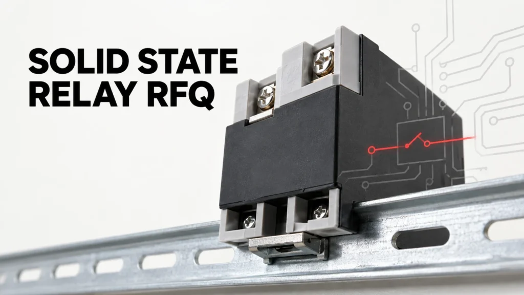
This checklist helps engineers and procurement teams request comparable SSR candidates. It focuses on the information to send and the model-specific evidence to require. It does not claim that one SSR can replace a contactor or another SSR without a circuit and installation review.
Define the load before the relay
State whether the load is resistive heating, a solenoid, lamp, motor, transformer or another device. Give normal voltage, operating current, frequency for AC circuits and the expected current waveform. Load type matters because inrush, inductance and commutation behavior vary. A relay suitable for one AC heater may not be suitable for a transformer or motor circuit with a similar steady current.
Provide starting or inrush current with duration and repetition if known. If it is unknown, flag the need for measurement or load-manufacturer information. Do not apply an illustrative inrush multiplier from a guide to a different real load without verification. The exact SSR's surge-current evidence must be compared with the duty imposed by the application.
Identify the minimum load current as well as the maximum. Some output technologies need sufficient current to switch or remain latched as intended. Very small loads may also respond to off-state leakage. Omron's SSR guidance explains why load type, minimum current and leakage need application review; exact thresholds depend on the model.
Distinguish AC and DC output technologies
State whether the load supply is AC or DC. An AC SSR based on a triac or thyristor output is not a generic DC load switch. A relay may have an AC control input and AC output, DC control input and AC output, or another combination. The input-side label alone does not define what it can switch.
Ask for the exact output-voltage range, frequency, off-state blocking, leakage, on-state drop and surge capability. For DC output applications, require an output technology and ratings specifically documented for DC. Do not infer DC capability because the controller provides a DC command signal.
Clarify whether the load circuit needs one pole, multiple poles or a specific phase arrangement. A single-phase SSR used in a multi-phase assembly needs a system design and protection review. The number of terminals on the case is not enough to establish how the load should be connected.
Specify the control signal and switching behavior
Provide the controller output type and its available voltage and current under on and off states. Confirm the SSR input operating range, polarity if applicable, input current and isolation information. A PLC output or temperature controller may have leakage of its own; test the combined circuit rather than assuming a nominal “24 V” label guarantees clean switching.
State whether zero-cross or random-turn-on behavior is needed for the AC load. Zero-cross switching turns on near an AC voltage zero crossing and may reduce switching noise in some resistive-load applications. Random-turn-on operation can be relevant for phase-control or other timing needs. Neither mode is universally preferable; the load and controller strategy decide.
Document the desired switching frequency and duty cycle. Frequent cycling can make an SSR attractive because there are no mechanical power contacts to wear in the same way as a contactor, but it also produces continuous on-state heat and may complicate protection or failure-state requirements. Compare the exact technology against the application rather than treating “solid state” as a blanket advantage.
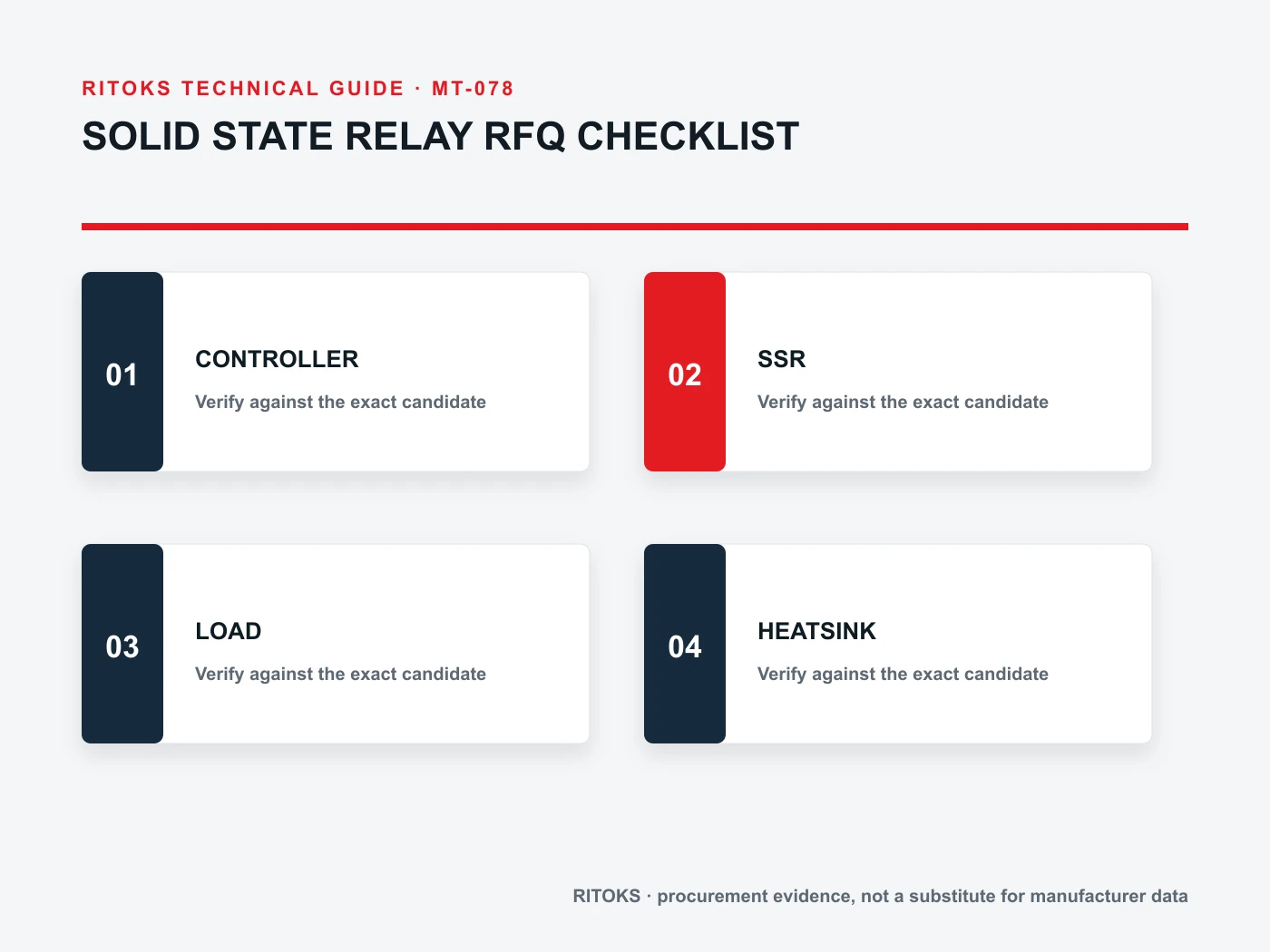
Account for off-state leakage and failure behavior
SSRs can pass a small off-state current. Sensitive lamps, indicators, PLC inputs and other low-power loads may glow, remain partially energized or fail to reset if leakage is not considered. Ask for the exact model's leakage data at the relevant output voltage and compare it with the load's release behavior. Do not assume an OFF command creates the same physical gap as an open mechanical contact.
Define the required response to SSR failure, including whether an independent disconnect or protective device is needed. Some semiconductor failure modes can leave a load energized. The system safety analysis should not rely on an SSR as a sole isolation device unless the exact architecture and approvals explicitly support the intended function.
Record who is responsible for fusing or short-circuit protection. SSR semiconductor elements can be damaged by fault energy faster than ordinary upstream protection acts. Obtain the manufacturer’s coordination recommendations for the proposed model and relevant fault level; do not infer protection from the current rating.
Give cooling information with the current request
An SSR dissipates power while it carries current. The heat depends on output technology and operating duty. Provide the maximum local ambient, enclosure temperature, airflow, mounting surface and whether a heatsink is already available. Ask for the exact-model derating curve or thermal instructions under those conditions.
Omron's SSR application guide links load-current ratings to ambient conditions and heatsink choice, and recommends confirming temperature under power application. That principle is transferable; Omron's particular sink examples and ratings are not specifications for a RITOKS product. Require the proposed SSR's own thermal data and mounting method.
Consider several SSRs mounted side by side. Their combined heat can raise the local air temperature. Document spacing and enclosure ventilation, then validate the assembled panel under representative load. A free-air laboratory rating should not be copied directly into a crowded sealed cabinet.
Specify package, terminals and service access
Send the allowed mounting footprint, height, terminal type, conductor sizes and available clearance. Indicate whether the product must mount to a PCB, panel or DIN rail. A PCB-mount relay and a panel-mount power SSR can both be called “solid state relays” while requiring very different mechanical and thermal treatment.
Ask for the exact terminal drawing, installation manual and any accessory part numbers. State whether status indication or diagnostic output is needed. If a replacement project is involved, photograph the existing label but also supply the circuit drawing; the old case may not reveal all electrical requirements.
RFQ comparison table
| Kolom RFQ | Masukan proyek | Bukti pemasok |
|---|---|---|
| Muat | Type, voltage, steady/inrush current | Output and surge ratings |
| Kontrol | Signal levels and switching strategy | Input range and operating mode |
| Off state | Load release and safety needs | Leakage and isolation data |
| Termal | Ambient, mounting and airflow | Derating and heatsink instructions |
| Physical | PCB/panel space and terminals | Dimension and wiring drawing |
| Perlindungan | Fault level and upstream device | Coordination guidance |
Use the same project inputs for every bidder. Record unknowns as unknowns and ask each supplier to identify assumptions in its proposal. A generic “equivalent” offer should not pass until output technology, thermal duty, leakage and package are checked against the actual application.
Check the installed switching cycle
Before release, test a representative load cycle with the selected SSR and cooling arrangement. Record on-state current, local ambient, case or sink temperature and the behavior of the load after the input command turns off. A short unloaded bench test may confirm control wiring but cannot verify inrush, sustained heating or leakage effects on the real load.
Include the controller's actual output in the test. An SSR may behave correctly with a laboratory supply while a PLC output or temperature controller has a different off-state leakage or pulse pattern. If the process uses rapid cycling, observe several cycles at representative temperature, not just the first cold start. Save the settings and test conditions so a later replacement can be checked against the original qualification.
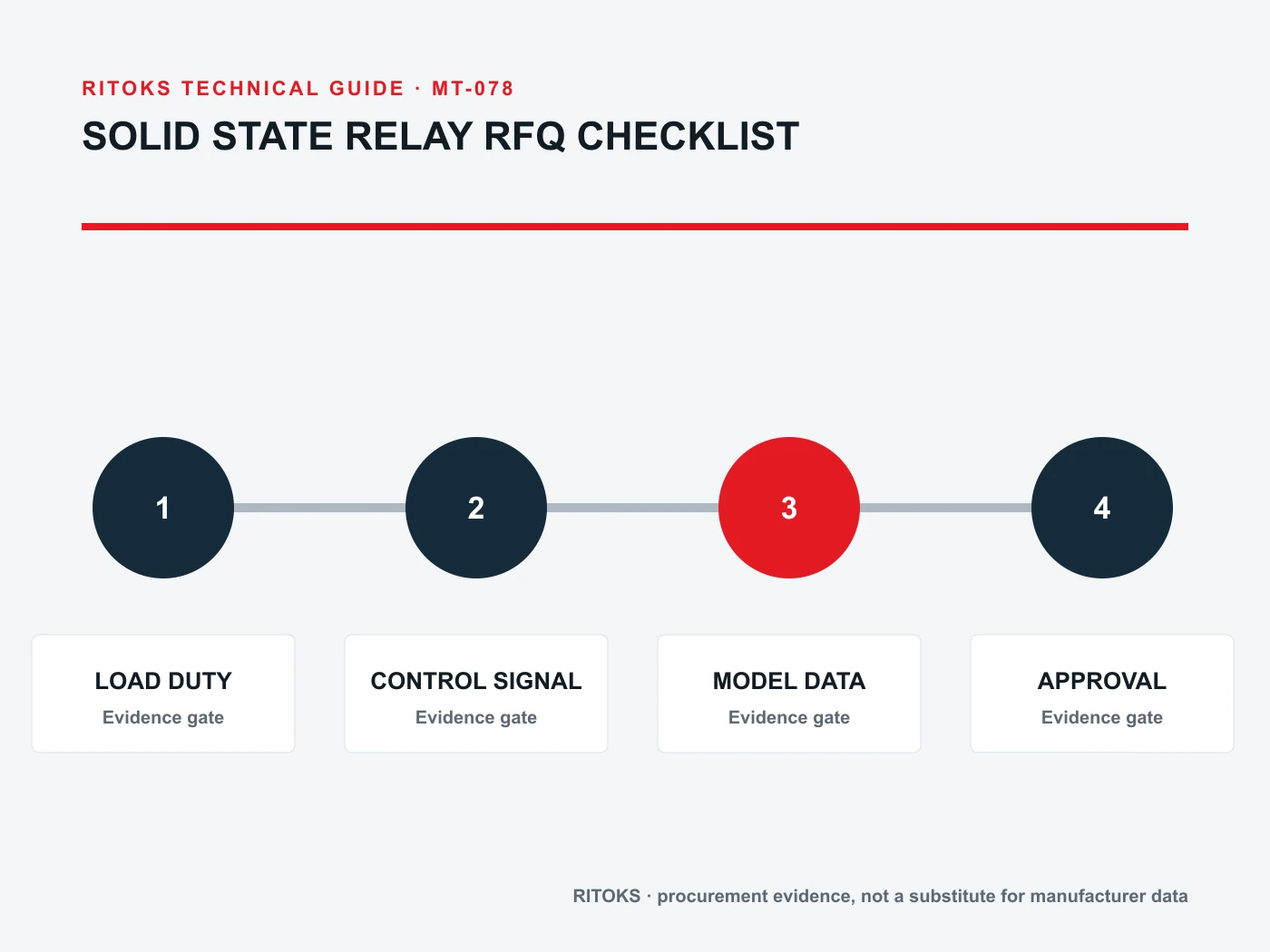
How to ask RITOKS for a candidate
Yang solid state relay category identifies the commercial family. The XSSR-P2 AC solid state relay page is a starting point for its documented application, not a guarantee that it fits every load, control output or heatsink arrangement.
Send the load waveform, controller signal, switching mode, leakage sensitivity, cooling plan and package constraints through Kontak RITOKS. Request an exact order code with input/output data, derating curve, wiring diagram and mounting instructions. Keep the control and load circuits visible in the same RFQ.
Pertanyaan yang Sering Diajukan
Does a DC control input mean the relay can switch DC?
No. Input and output specifications are separate. Verify the output technology and its voltage/current rating for the actual load supply.
Does an SSR truly turn the load off?
It can have off-state leakage. Verify that the connected load releases properly and provide independent isolation where the system requires it.
Is a heatsink optional whenever current is below the label?
Not necessarily. Check ambient, duty, mounting and the exact model's derating or heatsink instructions. Installed conditions decide the thermal margin.
Intinya
A solid state relay RFQ is complete only when load, control, switching, leakage, fault protection and thermal installation are all defined. Requiring exact-model evidence for each field prevents a relay with a matching ampere label from being treated as an approved substitute.