
AC Power Protection · Technical Explainer
Shared Neutrals and RCD Tripping: A Circuit-Mapping Checklist

Quick answer
A neutral returning through a different residual-current protection boundary can create an imbalance even when the connected equipment appears to operate normally. When an RCD starts tripping after a circuit alteration, check the ownership of its line and neutral conductors before ordering a replacement device. The useful deliverable is a verified circuit map, not a list of breakers that happened to be switched off during an incident.
Commission this work to a competent electrical professional under an approved isolation and inspection plan. Do not disconnect a neutral while energized, bridge neutral bars to suppress tripping, or increase residual-current settings to conceal an unexplained fault. This checklist organizes the evidence needed for a shutdown investigation; it is not a terminal-level wiring or testing procedure.
Define the protection boundary before naming the fault
An RCD assesses the balance of current through the conductors included in its sensing arrangement. In a single-phase circuit, current leaving through the monitored line should return through the corresponding monitored neutral. A return path outside that boundary can therefore be relevant to tripping without requiring a failed RCD. Hager identifies misplaced and combined neutrals among causes of unwanted operation in its modular circuit-protection FAQ.
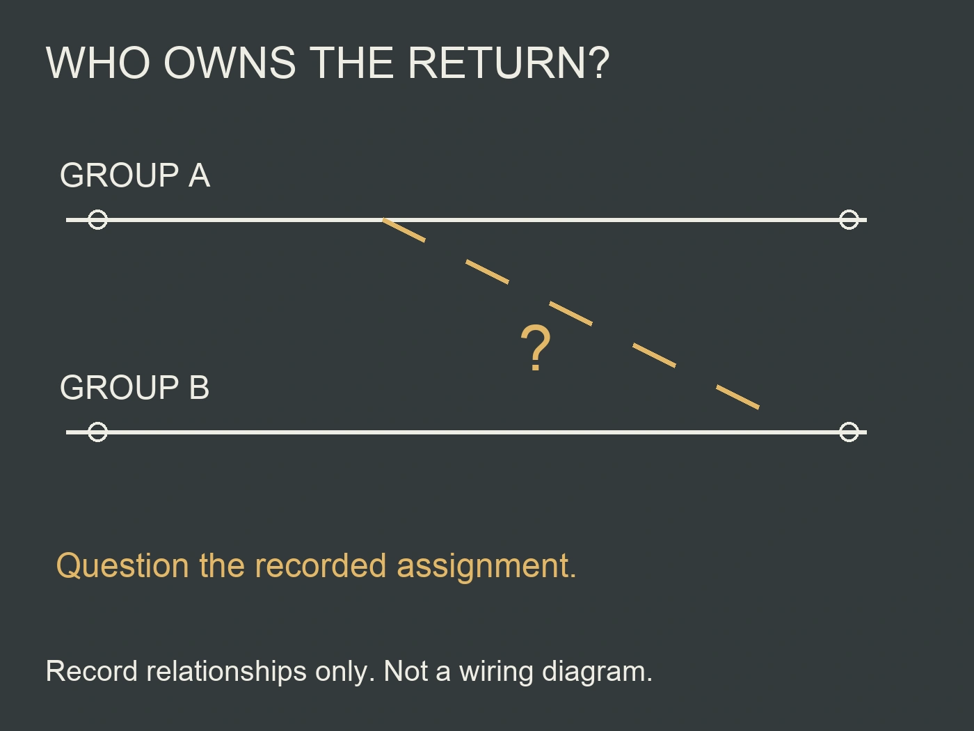
For a facility manager, the first question is which protective device owns each circuit. A board may contain one RCCB protecting several downstream circuits, several separate RCCB groups, individual RCBOs, or a combination. The position of a conductor on a common-looking bar does not establish which arrangement was intended.
Use “shared neutral” carefully. An intentionally designed multi-conductor circuit is not automatically equivalent to an accidental neutral connection between independently protected circuits. Its suitability depends on the actual architecture, protection, isolation and applicable installation requirements. Record that distinction rather than treating every neutral carrying more than one load's current as the same defect.
The practical concern here is an undocumented return path crossing the intended RCD boundary. Names such as borrowed, crossed or mixed neutral describe suspicions until the circuit has been traced and the design reviewed.
Collect the incident history without making live alterations
Ask the operator for the date, affected equipment and preceding changes. A lighting replacement, board extension, equipment relocation or conversion from grouped RCCBs to individual RCBOs can provide a useful starting point. Record whether one device or several operated and whether the event followed a particular switching action. These observations identify areas to investigate; they do not prove the conductor arrangement.
Preserve the latest circuit schedule, previous drawings, commissioning records and contractor change notes. Photographs already available from earlier work may help reconcile circuit identifiers. Do not ask unqualified staff to open a distribution board to obtain them. Where documents disagree, retain both versions and mark the discrepancy for the inspecting professional.
An equipment-related event may also involve genuine leakage, insulation deterioration or a transient disturbance. Hager discusses standing leakage as a separate cause of unwanted tripping. A neutral-mapping investigation should keep those alternatives open, not convert every trip after maintenance into a confirmed borrowed-neutral diagnosis.
Arrange shutdown access for the relevant distribution area and connected equipment. If tracing requires access to another tenancy, control cabinet or junction enclosure, settle that access before the visit. Otherwise the contractor may finish with only the board end identified and the actual return path unresolved.
Make isolation scope a prerequisite for tracing
Turning off a labelled final-circuit breaker does not, by itself, provide evidence that every conductor involved in a suspected shared-neutral arrangement is safe to handle. The tracing plan must consider the full area under investigation and all relevant sources, including auxiliary or alternative supplies where present.
The UK Health and Safety Executive requires safe working arrangements to address energy sources, prevent reconnection and prove exposed conductors dead with appropriate equipment. Its electrical FAQ also makes clear that RCD protection does not replace secure isolation. These are safety principles, not a universal switching sequence for every installation.
The competent person determines isolation points, lockout arrangements, verification method, instrument suitability and access boundaries under local rules and manufacturer instructions. For facilities operations, record who controls the isolation and what equipment remains outside it. Unexpected continuity or an undocumented supply should trigger a review of scope, not an improvised live experiment.
Electrical Safety First's Best Practice Guides include a dedicated safe-isolation guide and describe limitations of plug-in socket testers. An apparently satisfactory socket indication is not adequate evidence that the complete neutral ownership map is correct.
Build a line-and-neutral ownership register
Give each investigated circuit a stable identifier tied to its load or distribution function. Record the protective device and both ends of the relevant conductor route. For grouped RCCB protection, identify the group as well as the downstream breaker. For individual RCBO protection, identify the exact circuit and its associated neutral arrangement from that device's documentation.
The following is a project record structure, not a prescribed installation test form. A professional can adapt it to the inspection scope and local certification requirements.
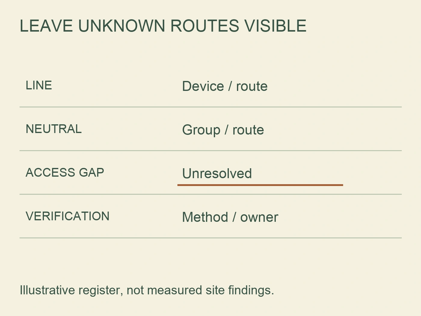
| Mapping field | Evidence to enter | Reason it matters |
|---|---|---|
| Identità del circuito | Board reference, circuit label and served equipment | Keeps the same circuit identifiable across drawings and inspections |
| Line ownership | Actual protective device and outgoing route | Establishes the intended supply-side protection boundary |
| Neutral ownership | Associated device or neutral group and traced route | Reveals whether the return belongs to that same boundary |
| Intermediate connections | Accessible junctions, control interfaces and branch points | Avoids assuming the board end represents the whole circuit |
| Alternative supply relationship | Documented source or explicit unresolved status | Supports a complete isolation and investigation scope |
| Verification record | Method, result, date and responsible professional | Separates observed facts from labels or assumptions |
A blank field means unresolved, not satisfactory. “Blue conductor on right-hand bar” is also not a complete ownership statement. Colour and physical position can support identification but cannot replace an established circuit relationship.
Give intermediate joints their own reference if several circuits pass through one enclosure. Record inaccessible sections explicitly. A map with a clearly identified unknown is more useful than a neat drawing that assumes the missing connection is correct.
Distinguish the arrangements found during the shutdown
Once the professional has obtained the necessary evidence, compare the actual arrangement with the intended design. The issue may be confined to a board termination, or it may originate farther downstream. The corrective scope depends on that distinction.
| Observed arrangement | Question for the technical review | Handoff implication |
|---|---|---|
| Circuit line assigned to one RCD group, neutral assigned to another | Does the verified return cross an unintended protection boundary? | Correct the documented ownership defect under an approved remedial plan |
| Protected circuit neutral associated with an upstream neutral connection | Is part of the return outside the intended sensing path? | Review both the route and termination against the exact architecture |
| A downstream connection joins otherwise separate neutral groups | Which circuits and operating conditions are affected? | Investigate the shared connection, not only the visible board terminals |
| Multiple loads share a documented circuit arrangement | Was that arrangement deliberately designed and appropriately protected and isolated? | Obtain design evidence before classifying it as an accidental cross-connection |
| Line and neutral ownership confirmed, tripping unresolved | Is another cause supported by inspection or test evidence? | Continue the fault investigation without replacing devices by assumption |
These rows are diagnostic categories, not permission to move a conductor. A neutral connected to the wrong bar may be a straightforward finding, but any remedial change still needs consideration of all served equipment and the original circuit design.
Do not remove protective-earth connections as a troubleshooting shortcut. Neutral ownership and protective-earthing integrity are different questions, and suppressing a trip is not an acceptable substitute for identifying the fault.
Treat an RCBO conversion as a mapping project
Consider a hypothetical conversion of two workshop circuits from one grouped RCCB to individual RCBOs. Before the change, both lighting circuit L1 and socket circuit S1 were listed under group G1. The proposed register now assigns L1 to RCBO-L and S1 to RCBO-S. A copied schedule still records both returns simply as “G1 neutral.” That older label is insufficient to establish their ownership in the new arrangement, even if it accurately described the old board.
A useful filled row is “L1: proposed line boundary RCBO-L; return route not yet traced beyond junction J2; old group G1 reference retained for comparison; current status unresolved.” The S1 row is “proposed line boundary RCBO-S; return ownership requires independent confirmation; access to J2 included in the planned shutdown.” No finding of an actual connection is claimed by these entries. Their value is that they expose exactly where the survey needs to extend, rather than allowing a board-end label to stand for the entire route.
If the competent inspection later establishes an unintended connection between the two returns at J2, the finding belongs to both circuit records and the approved corrective scope includes that joint. It is not sufficient to change a board label while leaving the downstream relationship unaddressed. If inspection instead establishes that the circuits are separate, retain that evidence and investigate other supported causes of the trips. The original suspicion should not survive as a confirmed diagnosis after contrary findings.
This example shows why a mapping survey can be worth scheduling before a conversion rather than only after unexpected trips. The design changes the protection boundaries, while the old record may describe only their common group. The extra survey cost buys a defined corrective scope and fewer guessed replacement orders. It does not guarantee fault-free operation or make the previous shared arrangement acceptable. The accepted design, safe-work method and actual inspection evidence still determine what can remain and what must change.
A board that previously used one RCCB for several circuits may conceal undocumented connections within that group. Installing individual RCBOs creates separate protection boundaries. A neutral arrangement that was not exposed by the former grouped arrangement may then produce a different operating symptom. That does not demonstrate that the new devices are defective or that the previous arrangement was acceptable.
Before conversion, specify a circuit-identification survey and document the intended neutral ownership after the change. Include the manufacturer's connection instructions, exact device references and the board manufacturer's assembly requirements. A sales description such as 1P+N does not establish every detail of neutral switching, lead routing or terminal use.
For sourcing discussions, RITOKS lists an RTX-RCA63 Type A RCCB e un PXB2Ln-63 1P+N RCBO. These are different protective architectures, not interchangeable remedies for an unidentified wiring problem. Request the documentation for the proposed configuration and submit it with the circuit map for design review.
No product link establishes compatibility with an existing enclosure, busbar or assembly. Nor does changing the RCD type resolve a neutral that crosses the intended sensing boundary. Keep the purchasing decision separate from the evidence that justifies remedial work.
Close the investigation with evidence, not a successful reset
The handoff should identify the finding, approved correction, affected circuits and remaining uncertainties. Record the revised circuit schedule and drawing revision alongside the relevant inspection and test results. The competent professional selects the necessary post-work checks for the installation; this article does not prescribe test currents, acceptance times or insulation-test connections.
A successful reset is an observation, not a complete acceptance record. Likewise, operation of a device's test button is not a trace of every neutral route. Confirm the specific issue that initiated the work and document the basis for returning the affected area to service.
Attach the updated register to the maintenance record so future alterations start with established circuit ownership. If a section could not be accessed, state the limitation and the next required action. Do not describe the entire installation as verified on the strength of a partial neutral survey.
Domande frequenti
Does a shared neutral always trip both RCDs?
Do not use the number of devices that trip as a definitive diagnosis. The outcome depends on the actual return path, connected loads and protective arrangements. Trace the circuit relationships and assess the recorded evidence. One observed trip does not rule out a cross-boundary connection.
Riferimenti
- Hager Australia. (n.d.). Modular circuit-protection FAQ. Relevant sections: RCCB/RCBO operating principle, misplaced or combined neutrals, and standing leakage. Retrieved October 2, 2026.
- Health and Safety Executive. (n.d.). Electrical safety: frequently asked questions. Relevant sections: competence, RCD limitations, working live, and making equipment safe to work on. Retrieved October 2, 2026.
- Electrical Safety First. (n.d.). Best Practice Guides. Relevant descriptions: safe-isolation procedures and limitations of plug-in socket-outlet test devices. Retrieved October 2, 2026.