
Current Transformers · RFQ Checklist
Current Transformer RFQ Checklist
A current transformer RFQ must identify the measurement purpose and the circuit into which the CT will be installed. “We need a 5 A CT” leaves open the primary ratio, accuracy, burden, opening, mounting and safety details that determine whether a quoted device can be used. A meter input and a protection relay may call for different CT evidence even when they surround the same conductor.
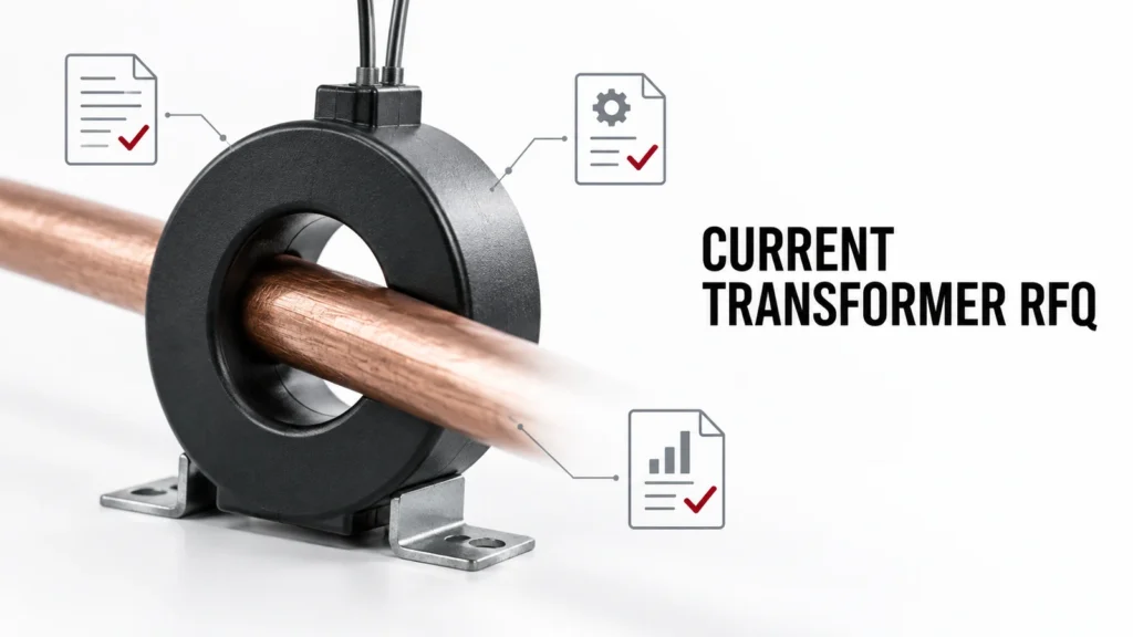
This checklist helps panel builders, metering engineers and procurement teams send a comparable inquiry. It does not choose a ratio or claim that a product fits an unreviewed installation. The final CT specification belongs with the meter or relay requirements and the physical panel drawing.
State the measurement function
Tell the supplier whether the CT is for energy metering, monitoring, control, protection or a combination. Name the receiving meter or relay and its input type. A conventional secondary-current CT is not interchangeable with a voltage-output sensor or a Rogowski coil without a compatible instrument interface. The receiving device documentation should define the required secondary signal and accuracy context.
For metering, explain the normal operating range and the accuracy needed over that range. For protection, describe the relay function and relevant fault-current range so the correct protection-class evidence can be reviewed. Do not assume a metering accuracy label predicts fault-current performance, or that a protection CT supplies suitable revenue-quality measurement.
Ask for the exact model's application scope and standard basis. IEC 61869-2 covers additional requirements for current transformers, but the standard name alone does not prove that a particular product has a requested class or installation rating. Require the candidate's current datasheet and identification.
Specify primary current and ratio clearly
Provide the conductor's normal, maximum and minimum currents, and the primary current expected at relevant fault conditions if protection performance is at issue. State the desired secondary current or other output format exactly as required by the receiving device. A ratio such as primary-to-secondary current is meaningful only alongside the intended operating range and connected burden.
Do not select the largest convenient ratio merely to avoid overload. If normal current occupies a small fraction of the CT's range, measurement quality may suffer depending on the model and class. Conversely, a low ratio cannot be approved without checking thermal, dynamic and relay requirements. The appropriate ratio is a system choice.
Ask whether the design requires a particular polarity orientation and phase identification. Mark the intended current direction on the single-line and panel drawing. Incorrect installation can reverse power-flow indication or affect directional protection. Include terminal-marking and wiring diagrams in the supplier response.
Calculate the connected burden
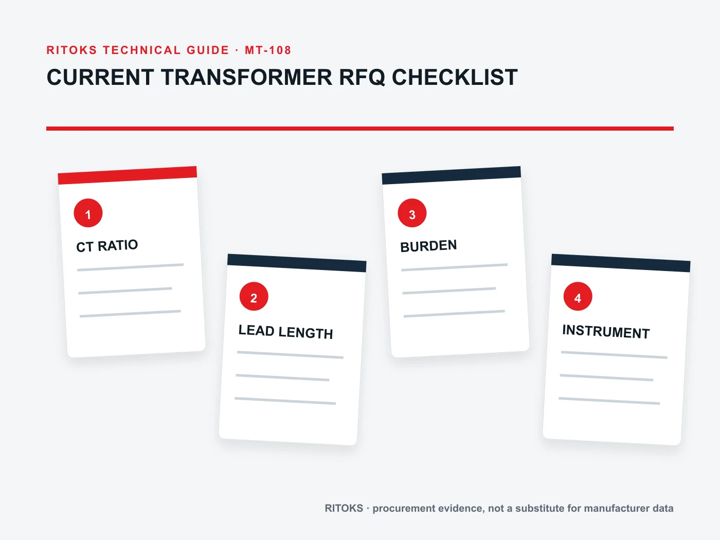
List every instrument, relay and wire run connected to the secondary. Include the input burden of the receiving device and the conductor resistance at the proposed length and size. A CT accuracy statement is typically conditional on a burden range; the actual secondary circuit must be checked against that condition.
Schneider Electric's CT selection guidance notes that the total dissipated power of the meter and cables should be assessed against the CT's stated burden. ABB protection documentation likewise discusses the relationship between CT burden and accuracy-limit behavior for protection applications. These sources support asking for the calculation; they do not supply the burden of the RITOKS model or the user's installation.
Distinguish a short secondary run from a long one, even if the same meter is used. Document terminal blocks, test switches and any shared secondary path. Do not leave cable length to be guessed after procurement, because the burden and installation method may change the appropriate candidate.
Define accuracy with its purpose and range
Provide the required metering or protection class from the project specification, plus the burden and current range at which it must apply. Ask the supplier to identify the exact class and rated burden on the proposed CT. A class printed on a generic family brochure may apply only to some ratios or constructions.
For protection, request the information the relay engineer needs about saturation and accuracy at high current. The relevant terms and limits should come from the exact CT datasheet and relay design. For metering, ask how accuracy behaves at the operating currents that matter commercially or operationally. Avoid combining the two use cases into one vague “high accuracy” phrase.
If the project includes several loads on one CT, confirm that the arrangement is permitted and include all burdens in the review. A convenient wiring change can change the electrical loading on the secondary. Make the final secondary circuit drawing part of the approval record.
Describe the physical opening and conductor
Provide the actual conductor or busbar dimensions, shape, insulation thickness, number of conductors passing through the opening and the space available around them. The CT window must accommodate the installed assembly, not merely a bare copper dimension. Record bend radius, neighbouring components and access for fitting and maintenance.
State whether the CT must be solid-core or split-core. A split-core format may allow retrofit without disconnecting the primary conductor, but it has its own mechanical closure and installation requirements. Do not treat a split-core CT as a generic substitute for a solid-core device without reviewing accuracy, mounting and closure instructions for the exact model.
Include mounting orientation, fixing method, rail or panel hardware and available depth. If the CT will be inside a crowded switchboard, ask for a dimensioned drawing and check terminal accessibility. The current transformer category identifies available commercial families; the physical fit still depends on a model drawing.
Address secondary-circuit safety in the RFQ
Conventional current transformers need an appropriate secondary circuit during primary energization. An open secondary on an energized CT can create hazardous voltage. Manufacturer instructions and site electrical-safety procedures must govern installation, testing and maintenance. ABB's CT installation manual explicitly warns against energizing a CT with an open secondary.
Ask whether a shorting terminal or test block is required and how it is to be wired. Provide the earthing approach specified by the project engineer. Do not assume every CT output technology uses the same shorting rule; identify whether the candidate is a conventional current-output CT or another sensor type.
Include a safe commissioning sequence in the panel documentation: verify polarity, check secondary continuity and burden, confirm test-switch operation, then energize according to the approved procedure. The supplier can provide model-specific instructions; the site team remains responsible for work methods and electrical isolation.
Send a structured request and require a structured response
| RFQフィールド | プロジェクトの入力 | サプライヤーの証明資料 |
|---|---|---|
| 機能 | Metering, protection or control | Exact-model application and class |
| Ratio/output | Primary range and instrument input | Ratio, secondary rating or sensor output |
| 負担 | Meter/relay plus lead calculation | Rated burden and accuracy conditions |
| Opening | Conductor dimensions and access | Window and mounting drawing |
| Safety | Test block and earthing plan | Secondary handling instructions |
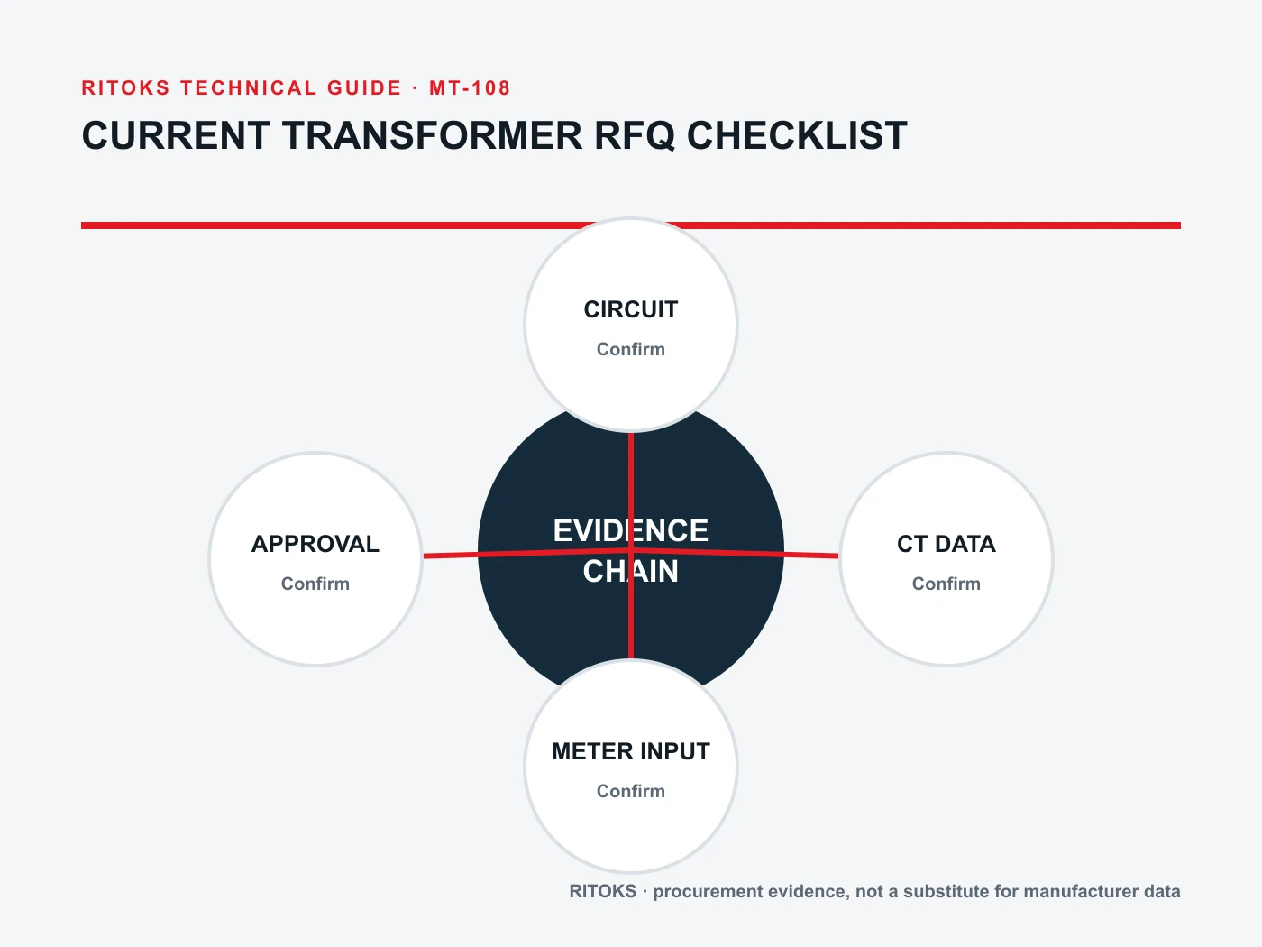
Ask the supplier to identify the exact order code, drawing revision, ratio, output, accuracy class, burden rating and installation instructions. If one field is unverified, mark the quotation conditional. This lets engineering compare proposals without mistaking a catalogue family name for an approved device. Confirm whether accessories such as a mounting bracket, secondary terminal cover or test block are included or must be ordered separately.
Compare RITOKS families without assuming interchangeability
その BH-0.66-60I family, DP split-core family そして GTA20L precision family illustrate different commercial options. Their product pages should be used to begin a model inquiry, not to infer that one shape, class or output is interchangeable with another.
Send the project checklist via RITOKSへのお問い合わせ and request the documents for the proposed exact model. If a supplier suggests a change from solid-core to split-core or from current output to another sensor architecture, route that proposal back to the meter or relay engineer before procurement approves it.
Questions buyers commonly miss
Is ratio alone enough for an RFQ?
No. The receiving instrument, accuracy purpose, burden, opening and mounting determine whether a ratio is useful in the installed system.
Can a CT secondary be left disconnected during operation?
Do not do so for a conventional energized current-output CT. Follow its manufacturer instructions and the site's approved shorting and isolation procedure. Sensor architectures differ, so identify the exact technology.
Will a split-core CT always fit an existing busbar?
No. Check the complete insulated conductor dimensions, closure clearance, mounting space and terminal access against the exact drawing.
結論として
A useful current transformer RFQ specifies function, current range, ratio/output, accuracy, connected burden, physical window and secondary safety arrangements. It also requires a response tied to an exact order code. Keeping those details together prevents a superficially matching ratio from becoming an unsuitable or unsafe substitution. Preserve the meter or relay input specification and the secondary wiring drawing with the selected CT so later panel revisions can be checked.