
技術リソース · 比較
Direct-Input vs CT-Input Panel Meters: Compatibility Questions
Direct-input and CT-input panel meters may show the same current value, but they connect to the power system in different ways. A direct-current input carries the measured circuit current through a meter or a documented sensing element; a CT-input meter reads a compatible secondary signal from a separately selected current transformer. The two architectures are not interchangeable merely because both displays show amperes.
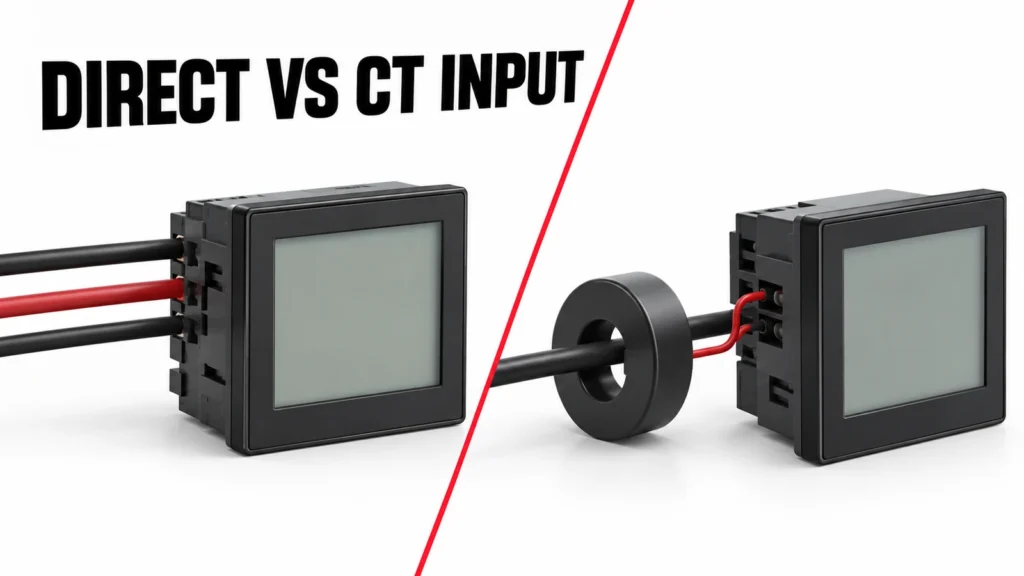
This comparison identifies the compatibility questions before a buyer specifies a meter. It does not assert that any named RITOKS model has a particular direct-current or CT-secondary range without exact documentation. The project drawing, CT and meter manuals must agree.
Define what “direct input” means in the proposed product
Vendors may use “direct connected” to describe current measurement through the instrument at a stated load-current limit, or voltage measurement directly across a circuit. These are different input questions. In an RFQ, write “direct current input” or “direct voltage input” and include a terminal diagram rather than relying on an ambiguous phrase.
For direct current measurement, the meter's rated current path, terminals, conductor size and protective arrangement must suit the feeder. The panel designer must account for installation and service work on that live power path. A compact indicator that can measure voltage directly may still require a CT for current; do not infer one capability from the other.
Request exact-model input limits and any overload or short-time withstand information relevant to the application. Do not route a high-current feeder through a meter simply because its display range can be set to a large number. Programmable scale and physical current capacity are separate.
What a CT-input meter receives
A conventional current transformer converts primary current into a specified secondary current for the receiving meter. Other sensors may provide voltage or a different output format. The meter must support that exact secondary signal. A CT ratio setting does not transform an incompatible input circuit into the correct hardware.
The CT is a separate component with its own primary ratio, secondary rating, accuracy class, burden, opening and installation requirements. The meter's accuracy claim alone does not define the combined measurement chain. The CT, connecting leads and meter input have to be checked together, especially when readings support energy or control decisions.
Schneider Electric's meter manuals show specific CT selection and ratio-configuration steps. These product examples demonstrate why a meter's hardware input and software setup both matter; they are not evidence that a RITOKS meter accepts the same secondary or ratio range.
Compare current range and physical fit
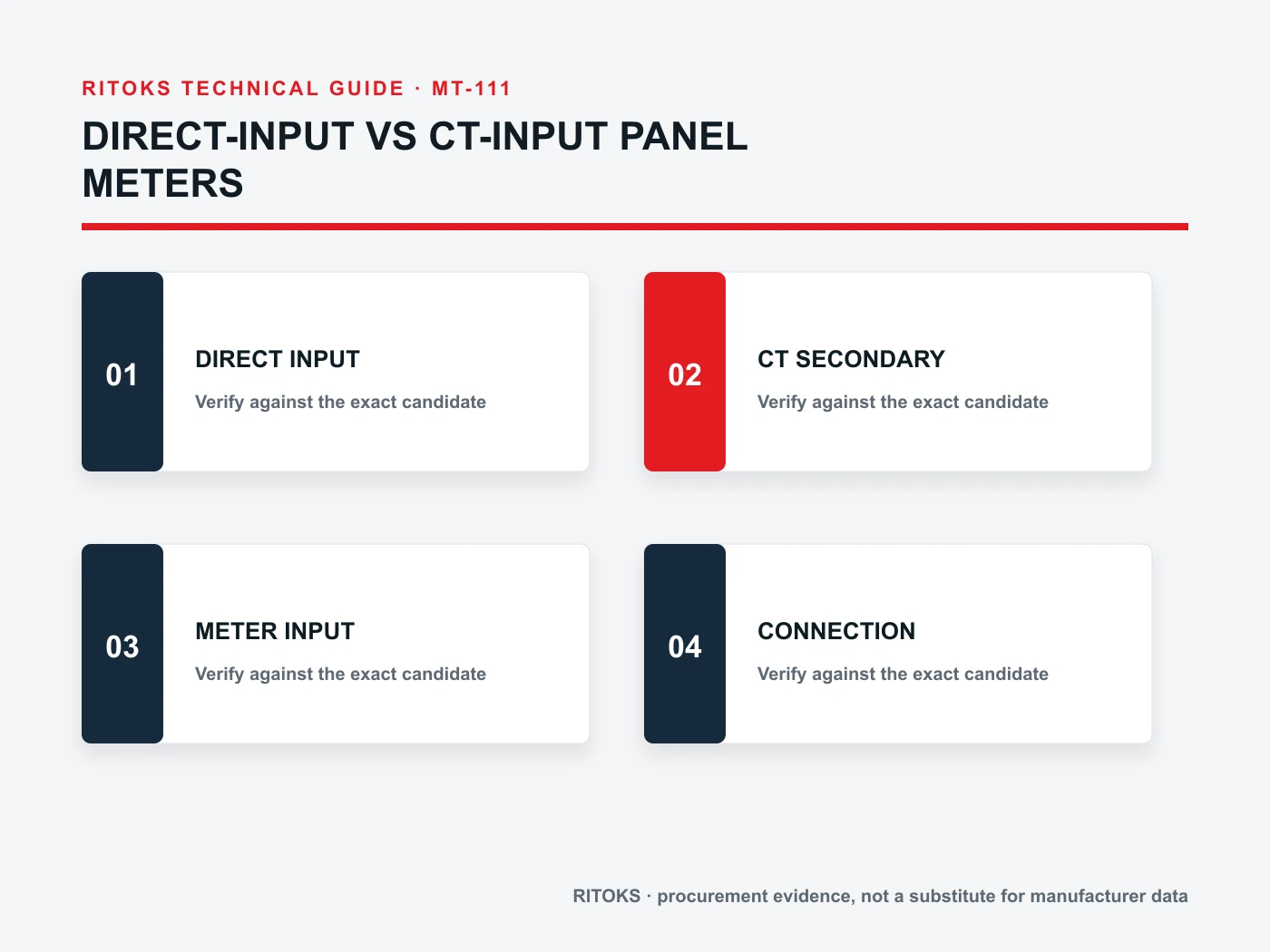
Direct input may be attractive for a smaller circuit because it removes a separate CT and ratio configuration, provided the exact meter is rated for the current and installation. For larger current paths, a compatible CT can allow measurement without carrying the full primary current through the instrument. Neither architecture is universally better; the circuit and maintenance plan decide.
A CT introduces physical requirements: conductor opening, solid or split core, mounting space and a secondary cable route. A direct-input meter introduces power-terminal space and conductor routing through or near the instrument. Compare both against the switchboard layout, not only the meter's front cutout.
For retrofit work, inspect the original connection. A panel meter may look identical externally while the rear terminals reveal a different input architecture. Photograph and document the existing wiring before ordering a replacement. An adapter plate cannot solve an incompatible current path.
Measurement quality and CT burden
With a CT-input meter, accuracy depends on the CT's ratio and class, the connected burden and correct wiring. Long secondary leads can add burden; a meter input can contribute as well. The project should calculate the total and confirm it lies within the CT's documented accuracy conditions.
A direct-input meter still has its own accuracy conditions: current range, waveform, ambient temperature and frequency where relevant. Compare the total installed chain at the values that matter, not only the display's number of digits. If the use is revenue or allocation, define the required metering evidence before choosing a family.
Incorrect CT ratio or polarity can produce readings that look credible but are wrong. The commissioning checklist should verify actual CT order code, primary/secondary markings, meter ratio setting and displayed value under a known operating condition. Do not treat a successful communications poll as proof of measurement accuracy.
Secondary-circuit safety changes the maintenance plan
A conventional current-output CT should not be left with an open secondary while primary current flows. Manufacturer instructions and site procedures govern shorting blocks, isolation and testing. ABB's CT installation documentation warns explicitly against an energized open secondary. Other sensor technologies may have different rules, so first identify the technology being installed.
Direct-input meters have their own hazard: the measured power circuit may pass through the instrument terminals. Isolation and conductor protection must be addressed in the panel design. Neither approach removes the need for a qualified installation and safe maintenance procedure.
Ask whether meter removal is expected during operation. CT-input arrangements may use a shorting test block, while direct-current measurement may require de-energization or another bypass design. The correct method belongs to the exact installation, not to a generic product comparison.
Comparison matrix for buyers
| 質問 | Direct-current input | CT input |
|---|---|---|
| Hardware | Meter carries defined measured current | Meter reads compatible CT secondary |
| 範囲 | Limited by exact meter current path | Depends on CT ratio and meter input |
| 精度 | Meter conditions and range | CT, leads and meter as a chain |
| Panel fit | Power conductor routing | CT opening and secondary wiring |
| サービス | Power-path isolation plan | Secondary shorting/test plan |
Use the matrix to frame document requests, not to score either architecture automatically. A meter and CT may be separately adequate yet incompatible together. The exact hardware input specification is the central compatibility check.
What the supplier should confirm
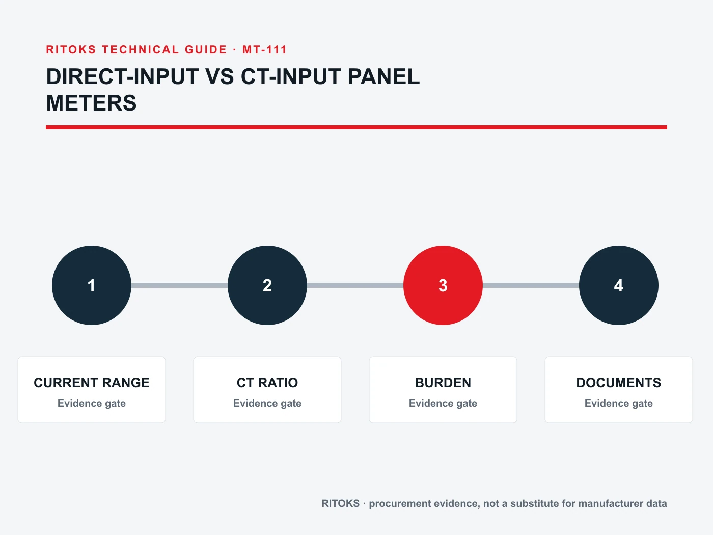
Send system voltage, current range, phase arrangement, measured quantity, desired accuracy, existing CT data if any, panel cutout and available wiring space. Request the proposed meter's exact input type, range, terminal diagram, auxiliary supply and configuration manual. If a CT is needed, identify a compatible exact model and its burden and installation documents.
その digital panel meter category includes different possible use cases. Review the D85 voltage/current family, multifunction meter family そして AD16-22 voltage display family as commercial starting points only. Do not infer current-input architecture from family names.
使用方法 RITOKSへのお問い合わせ to request exact documents. For a replacement, include the old rear-terminal photo and wiring drawing, not only the bezel photo. Record any proposed architecture change for engineering approval before procurement treats it as equivalent.
Commission the complete measurement chain
For a direct-input meter, confirm the actual conductor path, terminal identification, voltage connection and protective arrangement against the meter's wiring diagram. The meter's rated current range must cover the circuit under its intended conditions; physical terminal acceptance and conductor size are separate checks. Record the installed orientation and panel access so the display and isolation points remain serviceable.
For a CT-input meter, identify each primary conductor and its associated secondary pair. Mark the CT orientation and phase relationship before terminating the meter. Set the exact primary and secondary ratio specified for the installed CT, then check readings under a known load. Reversing a CT or crossing phase associations can create negative power or misleading totals even though current appears plausible.
Use a documented safe procedure for CT-secondary work. The secondary of an energized current transformer must not be casually opened; the project's shorting and isolation arrangement should be shown on the schematic and followed by qualified personnel. This requirement changes the panel's maintenance design, not just its initial wiring cost.
Compare the indicated current with an independent measurement or a controlled load where practical, then check voltage, power direction and cumulative energy over a defined interval. Document the load condition and the meter settings at the time of comparison. A single display snapshot cannot reveal a ratio error that only appears when the trend is interpreted later.
Account for expansion and replacement
A direct-input arrangement may be compact for a suitable circuit, but replacing the meter can require disturbing the measured conductor. A CT-input arrangement adds components, space and wiring while allowing the meter to be positioned away from the primary path when the system design permits. Compare future service needs with the original installation effort, rather than selecting only by unit price.
For a fleet of panels, maintain a schedule of CT ratios, accuracy data, polarity marks, meter order codes and configuration backups. A spare meter with the same front-panel dimensions may not accept the same secondary input or have the same setup procedure. Check the exact manual before using it as a replacement.
If the load may grow, obtain an engineering review of the full measurement chain. Do not simply raise a software ratio to keep the display within range; the physical CT, secondary wiring and meter input still have limits. Conversely, an oversized CT can reduce useful resolution at low operating current. The current profile matters more than a one-time maximum.
よくある質問
Can a CT ratio setting make a direct-input meter CT compatible?
No. First confirm the physical meter input accepts the CT's exact secondary signal. Configuration can scale compatible input; it cannot change input hardware.
Is CT input always more accurate?
No. Accuracy depends on the CT, its burden, the meter and installation. Compare the complete chain at the operating range.
Which is easier to maintain?
That depends on panel design. Direct input needs a safe power-path isolation plan; conventional CT input needs safe secondary handling and usually a test/shorting method.
結論として
Choose direct or CT input by the circuit current, instrument hardware, accuracy chain, panel fit and maintenance plan. The displayed number is the final output of those choices, not evidence that the two meter types are interchangeable.