
DC 소형 회로 차단기(MCB) · 기술 해설
DC Cable Protection Studies: Combine Breaker Curves with Cable Limits
Quick answer
A DC cable protection study needs three separate checks: the installed cable must carry its intended load, the protective device must respond appropriately across the relevant fault-current range, and the cable must withstand the energy passed before interruption. A breaker ampere marking or breaking-capacity headline cannot establish all three.
Collect the installed cable data, the exact breaker's applicable DC characteristics and a circuit-specific minimum and maximum fault assessment. Compare compatible evidence, including tolerances and operating conditions. Use DC clearing-energy data where required rather than extending an AC curve into a region it does not cover.
The deliverable is a traceable engineering assessment, not an attractive plot with guessed lines. This guide helps buyers and integrators request its inputs; it does not approve a cable size, breaker pairing or field fault test.
Define which cable and fault path the study covers
Begin with the actual single-line diagram and cable schedule. Identify the source, protected cable section, protective-device location, downstream equipment and relevant return or fault paths. A collection of product datasheets without this circuit definition cannot show what is protected.
Include different source contributions where applicable. A battery, PV array and controlled converter do not automatically provide the same fault-current behaviour. Ask the responsible engineer which operating states and fault locations must be evaluated, and which equipment information supports those states.
The study should also identify sections where conductor size changes, circuits branch or another source can feed the same cable. A result for the main outgoing feeder is not automatically a result for every smaller branch.
Give each assessment a cable identifier and drawing revision. This simple discipline prevents a supplier's curve for one feeder from being attached to a later drawing whose route, source or protective-device arrangement has changed.
Establish installed ampacity before studying faults
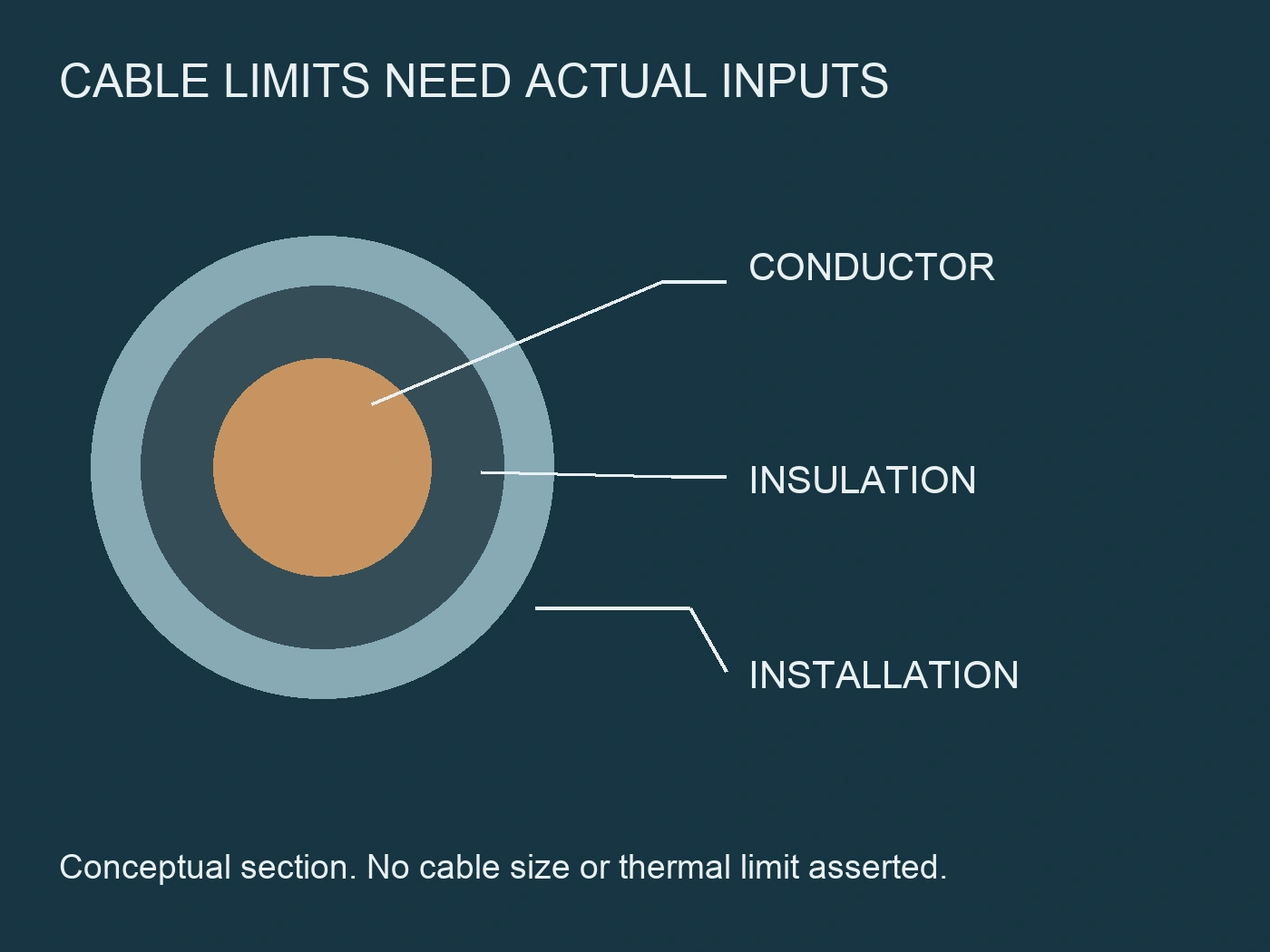
Cable current-carrying capability depends on its construction and installation, not cross-sectional area alone. Record conductor material, insulation, installation method, ambient conditions, grouping and any relevant enclosure or route restrictions. Use the appropriate documented basis for the installed arrangement.
Then identify the design load and the protective device's applicable current rating or setting. Do not confuse an MCCB frame size with its selected protection characteristic. Nor should an adjustable function be assumed merely because a device is moulded-case rather than miniature.
Schneider's Electrical Installation Guide distinguishes load current, permissible cable current and protective-device rating or setting. That distinction is useful here, while its three-phase AC examples and numerical coefficients are not imported as a completed DC calculation. Schneider Electric, practical protective scheme.
The overload review remains separate from the short-circuit review. A cable that carries the normal load satisfactorily can still require a different fault-energy assessment. Conversely, a successful short-circuit comparison does not prove that a grouped cable can carry the operating load continuously.
Request the exact DC characteristic package
Ask for the selected device reference, trip configuration and the documents that cover its actual DC application. Specify system voltage, applicable pole arrangement and polarity requirements without inventing a connection diagram. The manufacturer must confirm the arrangement used for its data.
The curve package should explain whether each chart represents trip operation, total interruption or a separate limiting characteristic. Record reference temperature, relevant loading conditions and tolerance bands. A single nominal trip line is not the same evidence as the complete operating envelope.
Schneider's PowerPact B documentation provides a useful model-specific warning: its AC and DC magnetic trip information differs. This does not establish a universal conversion factor or identical thermal behaviour for RITOKS breakers. It demonstrates why an AC-labelled chart needs explicit manufacturer DC application information before use. Schneider Electric, PowerPact B thermal-magnetic protection.
Keep miniature and moulded-case devices distinct. Their product-family identities help locate the right evidence, but do not substitute for that evidence. The RITOKS DC MCB family 그리고 DC MCCB family are separate document-enquiry routes, not interchangeable protection curves.
Assemble an input register before drawing the comparison
Use one register to expose missing information and mismatched assumptions. Require units, document references and configuration identities rather than relying on a spreadsheet cell labelled typical.
| Input group | Evidence to collect | Question the evidence must answer |
|---|---|---|
| Installed cable | Exact construction, section, route, installation and thermal basis | What continuous current is permitted in this installation? |
| Normal operation | Sustained load and relevant operating states | What current must the cable carry without inappropriate operation? |
| Breaker identity | Exact reference, trip configuration and DC arrangement | Which characteristic applies to the supplied device? |
| Fault envelope | Relevant locations, source states and DC current behaviour | What minimum and maximum duties must protection cover? |
| Clearing characteristics | Applicable time-current, tolerances and clearing-energy data | How much time and thermal exposure can remain before interruption? |
| Cable fault limit | Material, insulation, temperature assumptions and applicable method | What short-circuit exposure can the selected cable withstand? |
Assign unresolved entries to the supplier, cable manufacturer or engineering team. Do not turn unavailable data into zero exposure or a generic curve copied from a similar product. The register is complete only when its information corresponds to the same defined circuit.
Check the low-current end, not only the largest fault
A maximum fault value is important for interruption duty, but it does not establish operation at the smallest relevant fault current. The slower response region may be decisive for cable heating or the required protection outcome.
Ask the fault study to identify the relevant remote locations and source states. Where a source limits its current or changes its output during a fault, the engineering assessment needs that behaviour, not merely its normal output rating. A guessed constant current is not a substitute for the manufacturer's fault information.
Compare the appropriate breaker operating envelope with the cable limit across the assessed range. Where the upper operating-time tolerance matters, do not use the centre of a curve band as a guaranteed clearing time.
If the result is inconclusive at the low-current end, record the gap explicitly. The next action may be obtaining better source data, reviewing the protection concept or assessing a revised configuration. Raising the breaker's breaking-capacity figure does not by itself resolve slow or uncertain operation.
Use clearing-energy evidence in the limiting region
For high fault duties, a time-current chart alone may not provide the applicable thermal exposure. Obtain the manufacturer's DC clearing-energy information or other suitable evidence for the selected conditions and device arrangement.
The relevant thermal quantity is the integral of current squared over the complete exposure. Where current changes substantially, multiplying a prospective current squared by a guessed time can misrepresent that exposure. A trip threshold or mechanism operating time is not automatically the complete interruption duration.
Schneider's cable-withstand discussion illustrates comparison of protective-device let-through with cable thermal withstand under an identified short-time assumption. Its worked breaker and busway examples are not evidence for a RITOKS DC combination. Schneider Electric, cable short-circuit withstand.
Also distinguish prospective fault current from the current actually passed by a limiting device. State which quantity appears in each graph and which document establishes the relationship. Without those labels, even two charts with similar axes can be inappropriate to compare.
Build the cable limit from its actual assumptions
A conductor section does not define a complete thermal damage envelope by itself. The engineer needs the conductor and insulation information, relevant initial condition, permitted final condition and the validity of the chosen calculation method.
Where an applicable adiabatic assessment is used, the familiar k²S² relationship depends on those assumptions. Do not select a generic k value from an unrelated cable or apply a short-time model outside its justified range. Longer exposure or different conditions may require another assessment basis.
The cable manufacturer should identify relevant limitations that the curve study does not cover. Terminations, connectors and mechanical installation can introduce separate constraints. Cable conductor thermal withstand alone is not approval of every connection or support in the circuit.
For the procurement report, distinguish calculated cable capability from manufacturer-declared data and from completed assembly verification. Each can be useful, but they have different origins and scopes. An unexplained safe cable line hides those distinctions.
Record the three decisions separately
Make the conclusion readable without requiring the buyer to interpret a plotted overlap. State the configuration, evidence and result of each check, including any limitation or unresolved supplier request.
| 결정 | Evidence pairing | Incomplete conclusion to reject |
|---|---|---|
| Normal load and overload protection | Installed ampacity, load and applicable protection characteristic | Breaker amperes match cable catalogue amperes |
| Minimum relevant fault response | Fault-current behaviour and applicable operating envelope | Maximum fault exceeds instantaneous pickup |
| Maximum interruption duty | Actual DC duty and exact device application rating | Another variant has a higher breaking figure |
| Cable short-circuit thermal protection | Complete applicable clearing exposure and cable limit | Breaker can interrupt, therefore cable is protected |
| Installation scope | Connections, supports and protected-section definition | Cable thermal comparison approves the whole assembly |
| Change control | Revised inputs and affected conclusions | Same headline rating means any substitute is equivalent |
These are review questions, not universal numerical pass criteria. A qualified designer must establish the applicable criteria and decide whether the submitted evidence satisfies them.
Turn missing data into a precise supplier enquiry
For a selected RITOKS DC MCB configuration, request the exact DC time-current and clearing information needed by the cable study. Include the intended voltage, circuit arrangement, cable details and fault-study conditions so the supplier can respond to the real application.
Ask whether the document covers the exact ordered variant and whether additional DC application restrictions apply. A public product page may help identify a candidate, but its headline interruption rating is not an approval of the proposed cable.
If an upstream device is relied on for backup protection, require evidence for that exact documented association. Do not assume any high-rated upstream breaker makes any downstream device suitable. Keep backup protection and selectivity questions visible rather than hiding them inside a cable-energy plot.
Retain the accepted evidence with the order and drawing revision. When a supplier proposes a different breaker, cable or source configuration, identify which inputs and conclusions require review. No deliberate field short circuit is needed or authorised by this documentation workflow.
Work a thermal comparison without turning it into a cable approval
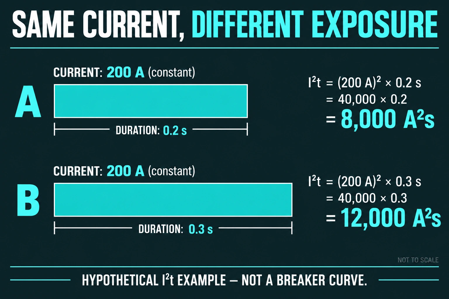
Use a hypothetical study entry C1 to see how exposure changes a finding. Assume, solely for teaching, that the designer has established an applicable cable thermal exposure limit of 10000 A²s for the stated short-time conditions. No cable size, material or k value is assigned to that limit. Also assume a rectangular passed-current history of 200 A lasting 0.2 s. The exposure is current squared multiplied by duration: 200² × 0.2 = 8000 A²s. These are invented constant-current inputs, not a RITOKS breaker curve, measured fault or recommended operating condition.
For that simplified history, 8000 is below the assumed 10000 A²s limit. C1 can record “illustrative thermal comparison below assumed limit,” but not “cable protected.” The example has not established installed ampacity, actual DC interruption duty, minimum-fault response, connections or even that a real limiting breaker passes a rectangular current. Those remain separate checks. The calculation is useful because it shows what a complete exposure comparison would mean if its actual evidence and method were applicable.
Change the duration to 0.3 s while retaining the hypothetical 200 A current. The exposure becomes 200² × 0.3 = 12000 A²s, now above the assumed limit by 2000 A²s. The peak current has not changed, yet the thermal comparison reverses. This is why a peak-current number and breaker ampere label cannot settle the cable study. It is not a prediction that a particular installed cable will be damaged at that value; its applicable limit and actual passed history have not been provided.
In a real limiting region, obtain the manufacturer's applicable total clearing-energy evidence rather than use this rectangular simplification as a shortcut. If a submitted chart covers only a trip mechanism interval, its number cannot automatically stand in for the complete exposure used in C1. Similarly, a cable limit copied without its initial temperature or method-validity assumptions does not become applicable just because its units match the chart.
Suppose fictional document E1 subsequently supplies the required DC total-clearing evidence for the selected variant, while cable document L1 still describes a different installation condition. C1 can close the breaker-evidence request and leave the cable-limit correspondence open. A larger headline breaking capacity would not address that remaining mismatch. Conversely, if L1 is confirmed but E1 applies to another voltage or pole arrangement, the protective-device comparison remains unresolved.
The alternatives have different consequences: retain a documented combination, review a different protection characteristic, or reassess the cable and installation. The responsible designer determines which changes address the actual failed or missing check. Procurement should not select among them solely by price, cross-section or the most favorable plot. Keep the completed normal-load, fault-response, interruption and thermal findings adjacent so a revised supplier offer can be reviewed without losing the reason for the original hold.
참고 문헌
- Schneider Electric. (n.d.). PowerPact B: Thermal-magnetic protection for circuit breakers. Model-specific AC/DC characteristic example. Accessed October 2, 2026.
- Schneider Electric. (n.d.). Verification of cable withstand under short-circuit conditions. Method assumptions only; AC worked combinations not transferred. Accessed October 2, 2026.
- Schneider Electric. (n.d.). Practical values for a protective scheme. Qualitative protection distinctions; AC examples not used as DC approval. Accessed October 2, 2026.