
AC Contactors for Industrial Motor Control · Technical Explainer
Capacitor Bank Step Switching: Why Reconnection Time Matters
Quick answer
A capacitor bank step should not reconnect simply because its contactor has opened and the power factor controller wants more compensation. The capacitor, discharge arrangement, switching device and controller must support the proposed off-time. Residual voltage is a separate condition from an open contactor, and an inrush-limiting contactor is not automatically a discharge device.
For a procurement or commissioning review, ask for the exact capacitor discharge requirement, the installed discharge circuit, the controller's same-step reconnection logic and the contactor's capacitor-switching documentation. Approve their combination, not an isolated timer value. There is no universal waiting time that this guide can assign to every capacitor bank.
The practical concern is repeatable operation. A bank may appear satisfactory during an initial start yet encounter a different switching condition when a recently disconnected step is requested again. Review that sequence before treating faster compensation as an improvement.
Separate four conditions before choosing a delay
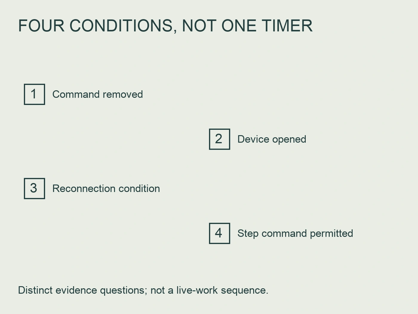
Four different questions are often collapsed into the phrase “the bank is ready.” Keeping them separate makes the review more useful.
| Condition | 요청할 증거 | What that evidence does not establish |
|---|---|---|
| Controller has removed the step command | Event record and output definition | Capacitor terminals are discharged |
| Switching device has opened | Approved circuit and relevant feedback | The discharge path is intact |
| Capacitor meets its reconnection condition | Exact manufacturer requirement and discharge design | The whole bank is safe to access |
| Step can be commanded again | Controller logic and coordinated component instructions | All operating conditions are acceptable |
This is a document-review table, not a sequence for working on energized equipment. Isolation, verification of absence of voltage and capacitor handling belong to the manufacturer's instructions and the site's qualified electrical procedures. A controller countdown is not a substitute for those procedures.
Also define what “same step” means. A controller may distribute operations among several steps. The delay relevant to one physical capacitor group should remain attached to that group even when the controller selects another output. A global switching interval and an individual step's reconnection restriction answer different questions.
Residual voltage belongs in the switching review
An open switching device interrupts the supply path, but a capacitor can retain stored energy. The residual condition before another closing operation therefore matters alongside the bank's nominal voltage and reactive power. A drawing should identify how the installed capacitor group discharges after disconnection and which documentation establishes its suitability.
ABB's official capacitor-switching guide states a residual-voltage condition before re-energization for its specified contactor families. The same guide describes damping resistors used during closing for the UA..RA design. These are manufacturer-specific conditions, not approval of a CJ19 variant or a universal reconnection voltage. The useful distinction is that controlled energization and off-state discharge are different design responsibilities. ABB, Contactors for capacitor switching.
A review should not assume that a component called a resistor serves both purposes. Ask where it is connected, when it participates in the circuit and which instruction describes its role. A closing-stage resistor arrangement may have a different connection sequence from a permanently connected or otherwise controlled discharge arrangement.
Component identification matters here. Record the capacitor's complete reference, rather than relying on the cabinet's total kvar marking. If a capacitor group has been replaced, the original panel drawing alone may no longer describe its discharge construction. Retain the replacement reference and the corresponding instruction revision in the equipment record.
Read controller timing as a sequence, not a single setting
The controller manual should explain what starts and ends the reconnection restriction. Is the interval counted from command removal, output opening, a recorded disconnection event or another defined condition? Do manual commands, fixed-step modes and recovery after loss of control power follow the same restriction? These questions should be answered by the selected controller's documentation, not inferred from a familiar menu label.
Schneider Electric's Varlogic R12/RC12 manual separates step configuration and timing within its programming structure. That supports checking the controller's documented timing function separately from general power-factor settings. It does not establish the settings or behavior of another controller. Schneider Electric, Varlogic R12/RC12 user manual.
Request the configured value and its rationale together. “Factory default” explains where a number came from, but not why it suits the installed capacitors. “The controller allows this value” describes a setting range, not permission to reconnect the bank under every condition.
For a multi-step installation, keep a simple output-to-capacitor schedule. It should identify the physical group, capacitor references, switching device, discharge arrangement and relevant controller configuration. A later technician should be able to find the instruction behind the setting without reconstructing the entire project.
Do not confuse damping accessories with discharge hardware
Capacitor switching is not ordinary motor starting. The review must consider the switching transient and the intended capacitor duty, as well as the steady operating condition. In a multi-step bank, the state of other connected groups is also part of the design context. A matching coil voltage alone is not an adequate contactor selection argument.
그 RITOKS CJ19 capacitor-switching contactor family identifies capacitor switching as its intended duty and requires the selected variant and inrush-limiting construction to be checked against the bank design. Its public family page does not establish an exact capacitor discharge time, a controller reconnection setting or blanket compatibility with a particular capacitor bank.
For a quotation, provide the selected capacitor group, operating voltage, step arrangement, controller and expected switching duty. Ask for the orderable contactor's applicable ratings, accessory construction and wiring information. Keep unsupported assumptions visible until the supplier returns model-specific evidence.
Do not interpret a capacitor-switching designation as permission for unrestricted rapid cycling. The design review still needs the capacitor instructions, switching-device duty limitations and the planned operating sequence. Any claim that a particular arrangement allows shorter reconnection should identify both the component and the documented conditions that make it possible.
Review a proposed faster setting without guessing
Consider a hypothetical panel review. An engineer proposes shortening the reconnection delay because compensation appears slow when an intermittent load returns. The record contains a controller setting screenshot and a contactor catalogue page, but the replacement capacitor instruction is missing.
The appropriate finding is not “the new delay is safe” or “the old delay must be correct.” It is that the evidence does not yet connect the configured interval to the actual capacitor and discharge arrangement. The review can proceed by recovering that instruction, confirming the fitted discharge hardware and checking how the controller handles a repeated request for the same physical step.
Suppose those documents subsequently support the proposed sequence. Acceptance should still identify the approved setting, applicable operating modes and responsible reviewer. If they do not support it, investigate the compensation design instead of using an unsupported timer reduction to mask the problem. The example provides no recommended numerical delay and describes no actual RITOKS installation.
A slow response may also be a control interpretation issue rather than a hardware limitation. Before requesting a faster device, establish whether the observed pause is a same-step restriction, a control response setting, a disabled step or another documented controller condition. This avoids procuring components against a diagnosis that has not been established.
Build a step-level evidence sheet
The following sheet can accompany an RFQ or commissioning review. Its purpose is to make unresolved items assignable rather than leave them hidden in a general approval statement.
| Record item | Required attachment or explanation | Review outcome |
|---|---|---|
| Physical step identification | Output number and capacitor-group reference | Each timer maps to the right group |
| Capacitor reconnection requirement | Exact instruction and revision | Condition identified without borrowing another model's value |
| Discharge arrangement | Circuit and installed component references | Intended off-state path documented |
| Switching arrangement | Contactor reference and capacitor-duty data | Selected construction matches the design review |
| Controller sequence | Same-step timing and relevant mode descriptions | Timing origin and exceptions understood |
| Proposed change | Existing value, proposed value and documented rationale | Authorized review or unresolved hold recorded |
| Maintenance record | Replacement parts and configuration changes | Evidence remains applicable to the installed bank |
A complete sheet need not be lengthy. The important feature is traceability: a reference, a relevant requirement and a clear disposition. Avoid attaching a large general catalogue without pointing to the applicable model and condition.
Distinguish technical acceptance from quotation completeness. A supplier can quote a contactor while capacitor discharge coordination remains unresolved. Likewise, a reviewed controller sequence does not establish the contactor's exact capacitor-switching rating. State which part of the decision each document closes.

Keep the approved sequence maintainable
The reconnection rule should survive controller replacement, capacitor replacement and ordinary configuration work. Include the approved step schedule in the panel's maintained documentation and retain the reason for any non-default timing. Otherwise, a later reset to defaults can silently remove the project's rationale even when no physical wiring changes.
A replacement request should identify which assumptions remain valid and which need review. A nominally equivalent capacitor may have different documented discharge requirements; a new controller may count its interval differently. Do not treat matching nameplate power as evidence that every part of the sequence is unchanged.
When troubleshooting, record observations before changing settings. Preserve the event order, affected output, operating mode and any recent component replacement. These details help separate a controller request from the physical readiness of a capacitor group. Measurements and any inspection of electrical equipment must follow approved qualified procedures; this guide supplies a review structure, not a live test method.
자주 묻는 질문
Is there one reconnection delay for all capacitor banks?
No universal value is assigned here. Use the exact capacitor, discharge-device, switching-device and controller instructions to establish the permitted sequence for the installed arrangement.
Does a capacitor-switching contactor discharge the capacitor?
Not merely because it is described as a capacitor-switching contactor. Identify the installed discharge path separately. Closing-stage inrush-limiting hardware should not be assumed to provide the required off-state discharge function.
Can a controller's minimum setting be used immediately?
The available setting is not evidence of suitability. Check the selected components' requirements and the controller's same-step logic, including applicable manual and recovery modes, before approving a change.
What should I send with a CJ19 enquiry?
Send the capacitor-group reference, step arrangement, voltage, controller, intended switching duty and discharge documentation. Ask RITOKS to confirm the exact CJ19 configuration and its applicable data; the public family listing alone does not close the coordination review.
참고 문헌
- ABB. (n.d.). Contactors for capacitor switching. Official guide, UA..RA operating principle and capacitor discharge conditions. Retrieved October 3, 2026. https://library.e.abb.com/public/ada5d05647748834c1257bcf003aa307/1SBC101140C0203%20ContactorsCapacitorSwitching_BR.pdf
- Schneider Electric. (n.d.). Varlogic R12/RC12 user manual. Official controller programming structure. Retrieved October 3, 2026. https://ckm-content.se.com/ckmContent/sfc/servlet.shepherd/document/download/0698V00000MzMFBQA3
- RITOKS. (n.d.). CJ19 capacitor-switching contactors. Live published product-family scope, checked October 3, 2026. https://ritoks.com/products/cj19-capacitor-switching-contactors/