
Rogowski Coils for Flexible Current Measurement · Technical Explainer
What a Rogowski Coil Measures When It Encloses Several Conductors
Quick answer
One Rogowski coil enclosing several conductors responds to their combined, direction-dependent changing current. It does not automatically report the arithmetic total of the conductors' separate RMS readings. Same-phase parallel conductors passing through the opening in the same reference direction can add; an outgoing and matching return conductor can cancel. Physical placement also affects the reading; see Rogowski coil positioning around busbars.
This is a measurement-definition question, not merely a question of whether a bundle fits through the loop. Before specifying the coil, identify which conductors are enclosed, their circuit relationships and the quantity the receiving instrument is intended to display.
The examples below are ideal conceptual explanations. They are not ZRC accuracy results, wiring instructions or approval to use a measurement coil as a residual-current trip system.
Start with the signed instantaneous sum
Choose a reference direction through the loop and use it consistently. A conductor's instantaneous current has a sign relative to that direction. The conceptual enclosed current is the algebraic sum of those signed values at the same instant.
For a simple ideal example, two enclosed conductors carry instantaneous currents of +40 A and +30 A in the chosen direction. Their signed sum at that instant is +70 A. If the second instead carries -30 A, the sum is +10 A. These hypothetical numbers describe only an instant; they are not RMS values or a selected coil's operating limits.
The polarity convention belongs to the measurement record. Reversing the coil reference can reverse the interpreted waveform polarity without changing the physical circuit. That matters when the measurement chain uses phase or signed current information, even if a magnitude-only display does not show the sign.
PEM's Rogowski technical notes explain the coil's changing-current response and integrated measurement principle. The direction-dependent summation used here is an ideal superposition interpretation, not a guarantee of exact real-world cancellation. PEM Rogowski technical notes.
Compare two enclosed conductors with the same physical appearance
Two cables inside one loop can represent very different measurements. The number of cables and their physical proximity do not establish their electrical relationship.
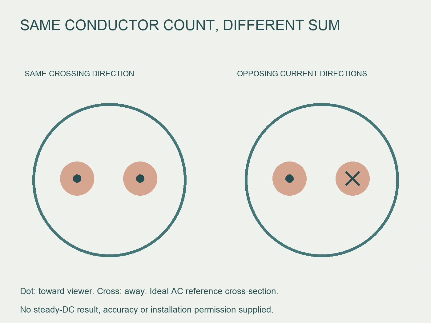
Consider two parallel conductors serving the same AC phase. If their currents have the same waveform shape and phase, and both cross the opening in the same reference direction, the ideal enclosed waveform is their sum. The two conductors do not need to share current equally for the principle to apply.
Now consider one outgoing conductor and its return. If their instantaneous currents are equal and opposite through the opening, their ideal enclosed sum is zero even while substantial current flows in each conductor. A small net result is therefore not evidence that neither conductor carries current.
| Pair inside the loop | Ideal relationship | Quantity represented by the signed sum |
|---|---|---|
| Same-phase parallel conductors, same crossing direction | Waveforms add with matching reference direction | Combined phase-current waveform |
| Matching outgoing and return conductors | Equal waveforms cross in opposite current directions | Zero net waveform in the ideal case |
| Outgoing and return with an unmatched path | Some current returns outside the enclosed set | Remaining net waveform, subject to the actual circuit |
| Conductors of different phases | Waveforms have different time relationships | Instantaneous resultant, not a sum of separate RMS magnitudes |
These are circuit interpretations, not installation permissions. The actual coil's application limits and the measurement chain still need verification.
Do not add RMS readings before forming the waveform
RMS is calculated from a waveform over a defined interval. The RMS of a signed sum is not generally equal to the sum of individual RMS magnitudes. First establish the resultant waveform; then consider the receiving instrument's RMS calculation and supported measurement conditions.
For an ideal pair of identical, in-phase AC waveforms traveling in the same reference direction, doubling the waveform also doubles its RMS value. For an ideal equal outgoing/return pair, cancellation gives a zero resultant and therefore zero RMS of that ideal resultant.
For different phase angles or waveform shapes, those shortcuts do not apply. A magnitude-only reading from each separate conductor loses information required to reconstruct the signed resultant. Two individually similar RMS values can correspond to quite different net measurements.
This is why enclosing three phases does not give a convenient “total three-phase current” by adding their nameplate currents. An ideal balanced three-phase set can have a zero instantaneous sum, although each phase carries current. That does not imply zero transferred power, zero conductor heating or a safe-to-touch circuit.
Any numeric RMS result needs the actual waveforms, measurement interval and supported processing. This article supplies no ZRC multi-conductor calibration or combined-current accuracy claim.
Treat cancellation as an interpretation, not an isolation test
Fluke's official 902 FC manual illustrates correct and incorrect AC clamp measurement arrangements, including the problem of enclosing opposing paths when the intended task is measuring a conductor's load current. This is a useful manufacturer illustration of cancellation; its meter specifications and safety instructions do not qualify a Rogowski coil. Fluke 902 FC manual.
A near-zero display can arise because the intended current was canceled by an enclosed return path. It can also reflect the measurement chain or its limits. The observed number alone does not establish the exact reason.
Consequently, do not use a low net-current reading to declare the installation de-energized. A cancellation-based measurement is fundamentally different from proving absence of voltage. It does not authorize touching, rerouting or disconnecting conductors.
If the intended quantity was one phase's combined load current but both that phase and its return were enclosed, the task definition is wrong even if the displayed number is stable. Correct the documented measurement scope through the authorized engineering process, not by treating stability as proof of a valid measurement.
Keep the coil and its integration chain together
A Rogowski coil's raw output is associated with change in enclosed current. Recovering the intended current measurement requires appropriate integration and signal processing within the measurement chain. A raw coil is not interchangeable with a conventional current transformer secondary or an arbitrary analog input.
The RITOKS ZRC flexible Rogowski coil family states that the coil does not include a built-in integrator and requires a compatible external integrator or meter input. That listing does not identify every compatible instrument or establish accuracy for the multi-conductor layouts discussed here.
Request the selected coil's output definition and the receiving input's supported sensitivity, integration, range and relevant operating conditions. Preserve the exact combination in the measurement record. Compatibility should be documented rather than inferred from a matching connector or a familiar current range.
The same principle prevents a DC misunderstanding. A Rogowski coil does not measure steady DC current by this changing-current principle. Observing a changing component or a transient does not establish the steady DC component of a battery current.
Likewise, a conditioned output described with a DC signal format does not necessarily mean the underlying sensor measures steady DC conductor current. Distinguish the output representation from the physical quantity sensed.
A net measurement is not automatically a protective system
An enclosed sum can be useful when the intended quantity is a changing net current. That physical possibility does not establish that the ZRC coil, integrator and receiving device form an approved residual-current protective arrangement.
Protection would require evidence for the complete application's required sensing, processing and interruption functions. This guide provides none of those qualifications. It does not specify a residual trip threshold, detection bandwidth or protective device.
Avoid naming a bundle measurement “leakage protection” merely because outgoing and returning currents may cancel. A nonzero resultant requires interpretation of the actual circuit and sensor performance. It is not, by itself, proof of leakage cause, a calibrated small residual or permission to trip equipment.
The buyer should distinguish a monitoring objective from a protective function in the quotation. A request to observe a net waveform and a request to perform certified fault protection are different requirements with different evidence needs.
Make a conductor-set record
A practical record describes the quantity before specifying hardware. It should let another engineer understand what crosses the opening and why that set represents the intended current.
| Record item | Information to retain | Error it helps expose |
|---|---|---|
| Intended measurement | Combined phase waveform, individual conductor or defined net waveform | Calling every enclosed bundle “total current” |
| Enclosed set | Conductor identities and circuit relationships | Including a return when only phase current was intended |
| Reference direction | Coil orientation and signed crossing convention | Adding a conductor that should subtract |
| Excluded paths | Relevant returns or other paths outside the set | Interpreting a remaining net signal without circuit context |
| Waveform/RMS objective | Processing quantity and interval, where applicable | Adding individual RMS magnitudes as if they were waveforms |
| Measurement chain | Exact coil, integrator/input and applicable documents | Treating a raw coil as a complete calibrated instrument |
This is not a live conductor-identification method. Use approved drawings and authorized identification records; on-site work must follow the equipment instructions and site safety arrangements.
One useful acceptance statement is “combined same-phase parallel conductors, same reference crossing direction, exact integration chain documented.” Another is “net waveform objective confirmed, but small-result accuracy remains unverified.” Both are more precise than “coil fits all cables.”
Calculate three different results from the same separate RMS readings
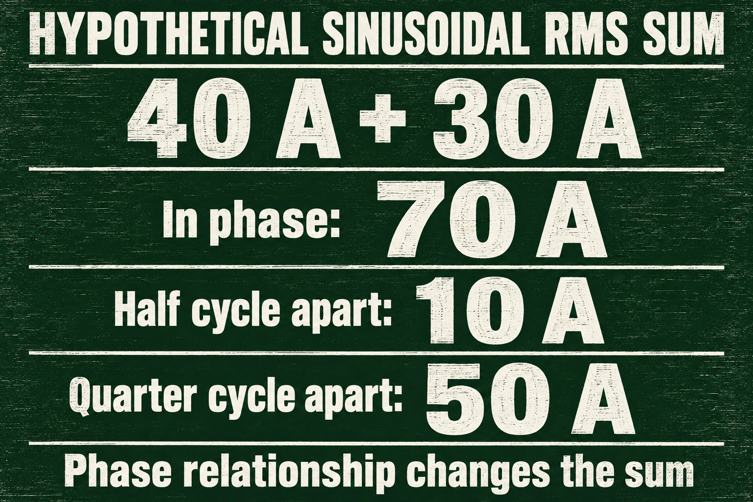
Consider two ideal sinusoidal AC currents at the same frequency. Conductor A has an RMS magnitude of forty amperes and conductor B thirty amperes. Both cross the loop in the same chosen reference direction. Assume complete-cycle evaluation, an appropriate ideal integration chain and no additional waveform components. These are fictional mathematical inputs, not a proposed ZRC range, real measurement or product accuracy test.
If the two waveforms are in phase, their signed waveform amplitudes add. The resultant RMS is seventy amperes. If B is shifted by half a cycle relative to A, the resultant RMS is ten amperes instead. The separate readings remain forty and thirty in both cases; the phase relationship changes the resulting quantity. Counting two conductors or adding their separate display magnitudes cannot distinguish these cases.
For a third case, shift B by one quarter cycle. Write the ideal instantaneous currents as forty times the square root of two times sine, and thirty times the square root of two times cosine, using a common time argument. Over complete cycles, the average sine–cosine cross term is zero. The resultant mean square is forty squared plus thirty squared: one thousand six hundred plus nine hundred equals two thousand five hundred ampere-squared. Taking the square root gives fifty amperes RMS, neither seventy nor ten.
The shortcut of adding separate RMS magnitudes happens to work in the first case because the ideal waveforms are aligned. It fails in the other two. For the quarter-cycle case, the square-root-of-sum-of-squares result follows from the stated sinusoidal relationship; it is not a general formula for arbitrary conductors, harmonics, unrelated frequencies or changing operating conditions. The real receiving instrument must process the supported resultant waveform over an appropriate interval.
Now change the buyer's objective while leaving the physical bundle unchanged. If the objective is combined current of two parallel paths on the same phase, documentation of their actual relationship supports evaluating that sum. If the objective is each path's individual RMS current, one enclosed resultant cannot recover those two individual values by itself. The same opening and conductor count can therefore satisfy one measurement definition but fail another without any change in mechanical fit.
A reported net value of ten amperes in the half-cycle example would also conceal substantial current in both paths if mistaken for their separate loading. It does not establish conductor heating, transferred power, absence of voltage or a safe work condition. Keep the intended waveform, phase relationship and processing objective in the conductor-set record so that a mathematically plausible display is not accepted against the wrong requirement.
Resolve the scope before accepting the displayed number
For same-phase parallel conductors, ask whether the intended quantity is their combined waveform and whether the documented measurement chain supports that application. For outgoing/return conductors, ask whether cancellation is intended or is concealing the load current the buyer wanted to observe.
If multiple phases or unrelated circuits are involved, retain their time relationships instead of assuming a sum of magnitudes. If the target includes steady DC, do not accept a Rogowski principle alone as satisfying that requirement.
For a ZRC inquiry, provide the conductor-set definition and the required measurement quantity alongside the selected coil and receiving instrument information. Request the available compatibility and application documents without claiming that the conceptual examples establish exact-model performance.
The essential decision is what the loop encloses electrically, not how many cables it contains. Once that is clear, the integration chain and its actual documented limits can be assessed against the correct measurement task.
Bronvermeldingen
- PEM. Rogowski technical notes. Changing-current response and integration principle. The mathematical examples here are ideal explanations, not PEM or ZRC measurement results.
- Fluke. 902 FC user manual (Italian edition). AC clamp-layout illustration, not Rogowski product qualification.
- RITOKS. ZRC flexible Rogowski coil family. Coil-only supply and compatible external integration/input requirement; no multi-conductor accuracy or residual-protection qualification inferred.