
PV Combiner Boxes for Solar DC Arrays · Technical Explainer
PV Combiner Box Heat Rise: Add Up Fuse, SPD and Connection Losses
Quick answer
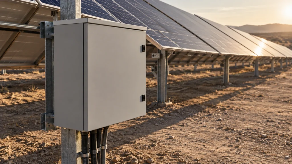
Assess PV combiner box temperature rise from the actual installed configuration, sustained circuit currents, component loss data, enclosure geometry and outdoor conditions. Fuse amperes, SPD discharge current and enclosure ingress protection are not a thermal approval for the assembled box. Build a loss schedule, locate the heat sources, then ask for an assembly verification whose assumptions match the intended site.
Keep three outputs separate: total internal electrical loss, internal air temperature and individual component or terminal temperature. A satisfactory average air temperature does not automatically establish that a tightly grouped fuse bank or output connection is acceptable. Conversely, a warm enclosure surface alone does not identify which internal component is responsible.
This guide provides a procurement and design-review framework, not a live testing procedure or a substitute for qualified PV engineering.
Define the configuration before calculating watts
Start with the exact combiner drawing and bill of materials. Record the number of populated inputs, protected poles, fuse-link and holder references, output switching arrangement, conductor sizes, terminal types and auxiliary equipment. Distinguish the supplied arrangement from optional components shown elsewhere in a catalogue.
De RITOKS LQX-N combiner box provides a commercial starting point for a configured enclosure enquiry. Its product-family information does not mean every separately listed RITOKS fuse, holder or SPD is already installed in that box.
Then define the load case. The current assigned to a string fuse is not automatically the current through the common output path. After currents combine, downstream conductors and connections carry the relevant aggregate current. Count losses against the actual schematic rather than multiplying every component by one assumed string current.
A useful configuration record also identifies unused ways and anticipated additions. A proposal for the initial populated arrangement is not evidence for a later fully populated version. Freeze the configuration being reviewed so the supplier and EPC team calculate the same assembly.
Build a loss schedule without double counting
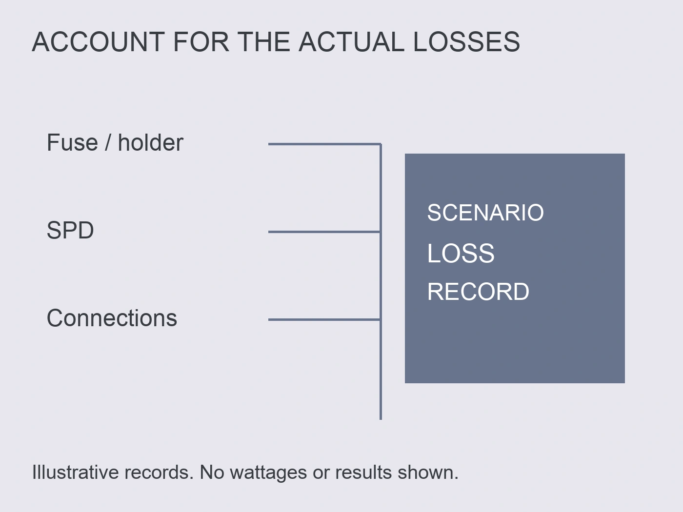
For each current-carrying item, obtain loss information at the intended operating condition. Useful evidence may include manufacturer power-loss curves, voltage-drop data, resistance data with stated conditions, or a documented measurement method. Identify whether the value covers one pole, one fuse link, a complete holder or the entire device.
For a resistive path, the basic relationship is P = I²R. It explains why additional current and increased connection resistance matter. It is not permission to treat an unspecified cold resistance as an accurate hot operating value. A fuse manufacturer's operating-loss information is preferable to an undocumented estimate.
Add each distinct loss once. If a manufacturer's complete-device value already includes its terminals, do not add the same terminal losses again. If only the fuse-link value is given, clarify whether holder contacts and external terminations remain outside that value.
| Budget line | Input needed | Accounting question |
|---|---|---|
| String fuse links | Exact references, quantities and operating-current loss data | Does the value apply to one link at this current? |
| Fuse holders | Contact losses or complete-assembly data | Are the installed links already included? |
| Output switch and collection path | Aggregate current and applicable device losses | Is the figure per pole or for the full arrangement? |
| Internal conductors and busbars | Actual route, section, material and applicable resistance | Are only the lengths inside the box counted? |
| Terminals and interfaces | Approved assembly method and available loss evidence | Are interfaces counted separately or within device data? |
| SPD and auxiliary equipment | Normal operating loss at the selected conditions | Is standby or continuous loss available, rather than surge ratings? |
Mark an unknown as unknown. A blank cell converted silently to zero makes the total look more certain than the evidence supports. Record the owner and required document for each missing input.
Treat fuse and holder losses as a matched-system question
A fuse link and its holder form a physical and thermal interface. Review dimensional compatibility, permitted fuse dissipation, contact arrangement and temperature-related application information together. A holder's current marking alone cannot answer every one of those questions.
The separately listed 10×65 mm PV fuse-link family en 10×38 mm PV fuse-holder family are different dimensional architectures. They are sourcing references, not a matched pair. Do not combine them in a bill of materials or assume either is the installed component in an LQX-N configuration without the correct assembly documentation.
Also distinguish a declared power-dissipation figure from an operating loss curve. Without its test condition and current basis, that figure should not become a fixed per-fuse contribution for every load case.
Mersen's photovoltaic protection note explains the influence of prolonged elevated ambient temperature on fuse behaviour. The note is dated 2018 and discusses the 2017 NEC; its numerical sizing rules are not adopted here as universal current guidance. Its relevant lesson is to obtain temperature-related application data for the selected fuse and actual environment. Mersen, Photovoltaic Protection Note 5.
Keep SPD discharge ratings outside the continuous heat budget
An SPD's impulse discharge-current rating describes a surge duty, not the sustained current flowing through the combiner's output conductor. It cannot be substituted into a normal-operation heat calculation.
Ask for the exact SPD reference, normal power dissipation or leakage information at the applicable operating voltage, and any associated monitoring or auxiliary load. Where the required normal-loss figure is not published, request it rather than inferring watts from a discharge-current headline.
De RITOKS PV DC SPD family includes different voltage and arrangement options. Selecting one option requires the actual PV circuit and protection design. A higher voltage marking on an optional SPD or fuse does not upgrade the voltage rating of an assembled combiner box.
Surge performance and normal thermal performance therefore belong in related but separate evidence files. Neither replaces the other.
Total loss is only the first thermal input
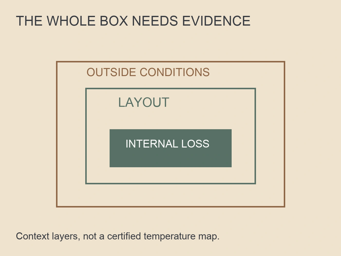
Two assemblies with the same total watts can have different temperature distributions. A concentrated fuse bank, an output connection above other heat sources, or obstructed internal air space deserves attention even when the overall loss total is unchanged.
Record component positions and the available enclosure surfaces. Mounting against a wall, nearby equipment or site structures can change the cooling conditions represented by a calculation. Cable ducts, barriers and densely grouped devices should appear in the reviewed layout, not only in the final installation photographs.
Rittal's enclosure-calculation overview identifies enclosure surface area and internal and external temperatures as calculation inputs, alongside equipment heat-loss information. This supports requesting a geometry-specific assessment rather than choosing cooling equipment from a watt total alone. It does not establish that a particular RITOKS box has passed that assessment. Rittal, enclosure climate-control calculation overview.
A local terminal temperature and a bulk air temperature answer different questions. Ask which locations are assessed and which component limits are applied. Do not accept an unexplained single temperature as a complete map of the assembly.
Add solar exposure as a separate site condition
The weather-service ambient temperature is not a complete thermal description of an exposed rooftop combiner. Record orientation, expected shading, enclosure construction, installation clearances and the site's relevant solar-exposure conditions.
Rittal's outdoor-enclosure discussion distinguishes internally generated heat from solar heat gain and describes purpose-designed double-wall solutions. That is a manufacturer example, not a claim that the LQX-N has the same construction or cooling performance. Rittal, outdoor enclosure thermal design.
For procurement, separate the electrical loss schedule from the external thermal assumptions. Solar heat is not a fictitious extra fuse loss. The assessment should explain how it treats both contributions.
If a report assumes permanent shade, identify the physical feature providing that shade and whether it persists during the critical operating period. If it assumes unrestricted cooling surfaces, compare that assumption with the proposed mounting. An enclosure rating is not a reason to ignore this mismatch.
Request assembly verification, not a collection of ratings
IEC's public description of IEC TR 60890:2022 identifies a calculation method for internal air temperature rise and notes considerations including uneven power distribution, solar radiation, enclosure materials and adjacent walls. Only that public description is cited here, not the full report or a completed compliance assessment. IEC TR 60890:2022, public scope description.
The responsible assembly designer must determine the applicable verification route and its limitations. A calculation or test report should identify the actual design, loading, environmental assumptions and acceptance basis. Component datasheets remain necessary inputs, but they are not a substitute for the assembly result.
| Review evidence | What should be traceable | Reason to hold acceptance |
|---|---|---|
| Configuration record | Drawing revision, populated ways and exact device references | Report covers a different population or substituted parts |
| Loss schedule | Current basis, quantities, source data and included interfaces | Unexplained zero entries or duplicated device losses |
| Environment record | Ambient, solar treatment and mounting assumptions | Shaded assessment offered for an exposed installation |
| Layout assessment | Heat-source locations, spacing and obstructed surfaces | Final arrangement differs from the evaluated layout |
| Verification result | Method, assessed temperatures and applicable limits | Only a general enclosure or component rating supplied |
| Change record | Reassessment of affected assumptions after substitutions | Extra inputs or auxiliary equipment added without review |
The acceptance package should let another engineer reconstruct the reasoning without guessing which catalogue variant was used.
Fill a loss budget and change one operating assumption
Imagine a fictional combiner configuration containing six installed fuse-link-and-holder assemblies, one collection/output path and auxiliary equipment. The assumed operating data are 2 W per fuse link plus 1 W per holder, 4 W for the output path and 2 W for auxiliaries. These are invented teaching inputs, not LQX-N component losses, verified operating currents or an installed bill of materials. The selected SPD's normal operating loss is initially unavailable.
The fuse-and-holder subtotal is six times (2 + 1), or 18 W. Adding the distinct output and auxiliary lines gives a known subtotal of 18 + 4 + 2 = 24 W. The total must be recorded as "24 W known electrical loss plus unconfirmed SPD loss," not "24 W complete assembly loss." An unknown does not become zero because the SPD is small or its surge rating is large. Other omitted current-carrying interfaces would also need explicit treatment before the budget could be complete.
Now suppose the same fictional supplier provides a complete link-and-holder loss value of 3 W per assembly at the stated operating condition. It replaces the separate 2 W and 1 W entries; it is not an extra term. Six times 3 W still gives 18 W. Adding all three descriptions would incorrectly count six times (2 + 1 + 3), or 36 W, for the same loss scope. This accounting correction changes the spreadsheet, not the physical temperature of the box. The inclusion basis must remain visible beside the manufacturer's data.
For a separate sensitivity exercise, assume the 4 W output-path value represents a purely resistive loss at 20 A with unchanged operating resistance. Changing its current to 25 A multiplies that line by (25/20)² = 1.5625, making it 6.25 W, an increase of 2.25 W. This conditional calculation applies only to that assumed path. It does not authorize scaling every fuse or SPD value by the same factor, keeping temperature-dependent resistance constant in a real box, or assuming the revised load is permitted.
The changed output current must therefore reopen the complete operating scenario rather than produce a new approved total by editing one cell. Fuse losses require their relevant current and temperature basis, auxiliaries need their own duty, and the SPD loss still needs evidence. If a fictional matching-condition SPD response later supplies 0.8 W, the original scenario's identified subtotal becomes 24.8 W. That closes the named missing line only; it is not a measured cabinet loss, a thermal margin or an enclosure rating.
Finally, keeping 24.8 W unchanged while moving the fuse bank beside the output connection does not establish unchanged local temperatures. Heat-source distribution and enclosure/site conditions still determine the assessment. A shaded calculation cannot be accepted for an exposed mounting solely because its electrical subtotal matches. The useful purchasing output is a traceable loss schedule with inclusion boundaries and scenario revisions, followed by matching assembly thermal evidence. No temperature rise, safe component temperature or cooling remedy is inferred from this arithmetic.
Turn the findings into an RFQ decision
Send the supplier the proposed string configuration, operating-current basis, site conditions and exact documentation gaps. Ask for a configuration-specific response instead of a general assurance that the box is suitable for outdoor PV use.
If the assessment identifies insufficient thermal margin, request a revised design with its supporting evidence. Possible design changes must be evaluated against electrical protection, enclosure integrity, serviceability and the applicable assembly requirements. Opening vents or adding a fan to an already specified sealed enclosure is not an automatic field remedy.
Do not increase fuse amperes merely to avoid heat-related operation. That can conflict with the protection requirements of modules, conductors and equipment. A revised fuse selection needs a renewed protection and thermal review, not just a new entry in the heat spreadsheet.
Finally, retain the accepted drawing and thermal evidence with the procurement order. This prevents a cheaper substitute with different losses from being treated as equivalent solely because its voltage and current markings look similar.
Bronvermeldingen
- IEC. (2022). IEC TR 60890:2022: Public scope description. Public abstract only; full technical report not consulted. Accessed October 2, 2026.
- Mersen. (2018). Photovoltaic Protection Note 5: Sizing Fuses for Photovoltaic Systems per the National Electrical Code. Historical 2017 NEC context; qualitative ambient-temperature discussion used. Accessed October 2, 2026.
- Rittal. (2023, June 14). Free Calculation Program for the Climate Control of Enclosures. Accessed October 2, 2026.
- Rittal. (2026, July 7). Beyond Weather Protection: Rethinking Outdoor Enclosure Design. Accessed October 2, 2026.