
Electrical Measurement & Monitoring · Technical Explainer
Commissioning a Three-Phase Rogowski Measurement Chain
Quick answer
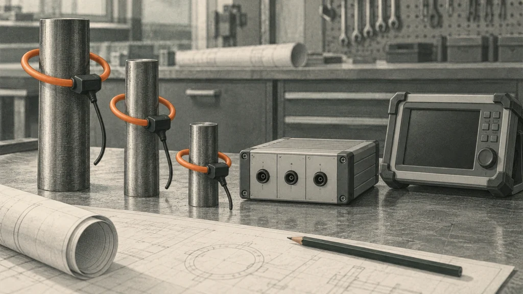
A three-phase Rogowski measurement installation can produce plausible current readings while its phase identities, direction convention or receiving configuration are wrong. The useful commissioning record follows each channel from the actual conductor through the coil and integrator to the receiving instrument. Where power measurement is intended, it also connects that current channel to the correct voltage reference.
The aim is a traceable correspondence, not a quick declaration that the screen has numbers. Establish the exact installed equipment, supported output type, required configuration and manufacturer commissioning procedure before interpreting the result. A common-looking connector does not establish compatibility, scaling or phase relationship.
This guide is a documentation and evidence framework for qualified commissioning personnel. It does not authorize applying a probe to hazardous live equipment, swapping energized leads, injecting current or opening a switchboard. The selected manufacturer's instructions and the project's safe-work process govern installation and testing. No universal terminal assignment, coil direction or acceptance tolerance is supplied here.
Confirm which output the chain actually provides
A raw Rogowski coil signal needs the appropriate measurement chain. PEM's Rogowski explanation describes the coil output as related to the rate of change of current and explains the role of integration. That basic principle does not establish the scaling, bandwidth or interface of a particular offered coil and integrator.
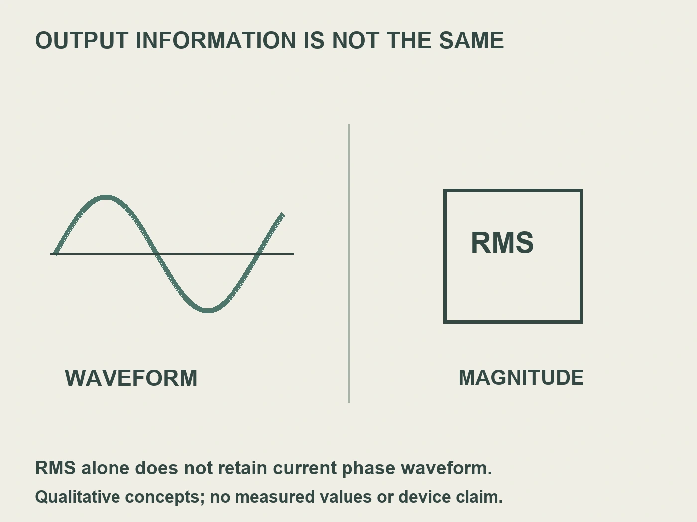
Distinguish a waveform-preserving current representation from an RMS-conditioned output. PEM's RCTi-3ph description en RCTrms-3ph description provide examples of those different output purposes. They are separate manufacturer products, not evidence that every three-channel integrator supplies both types.
This distinction matters before power analysis. A scalar RMS current signal does not by itself retain the instantaneous current waveform or its phase relationship to voltage. If the project requires signed power, power factor or waveform analysis, ask whether the whole selected chain provides the required information to the receiving instrument. Do not infer those capabilities from the words “three phase” on an enclosure.
Establish the installed identities first
Record the coil identifiers, integrator identity, output variant and receiving instrument. Include the applicable instruction revision and any settings that define scale or output behavior. If the three coils are supplied as a matched assembly, preserve that relationship as documented rather than treating every flexible loop as interchangeable.
Compare the receiving input requirements with the supported integrator output. The review needs the actual electrical interface and configuration, not only a nominal range in a catalogue. A voltage-output chain and another conditioned interface should not be connected or configured by analogy. Obtain clarification where the provided documents do not resolve the pairing.
Before making changes, retain the installed configuration as found. That record can be useful when diagnosing a discrepancy or reviewing a replacement. It is not an instruction to retain an unsafe installation. Qualified personnel should resolve the safe-work conditions and use the supported procedure, while the documentation preserves what was observed and what was subsequently accepted.
Build a channel correspondence record
Start with the project's conductor identities. Follow each identified conductor through its coil, the integrator channel and the receiving channel. Use the manufacturer's actual identifiers in the working record. Do not relabel terminals in a way that could conceal the original connection or imply a universal Rogowski wiring scheme.
For a power-measuring instrument, add the applicable voltage reference for each current channel. Accuenergy's AcuCT Flex installation guidance explicitly addresses orientation and correspondence with the appropriate phase/line voltage for its equipment. Its particular wire and shield instructions are not transferred to other manufacturers' products.
The following is a record framework. The phase names are project identifiers, not terminal numbers or a recommended wiring arrangement.
| Project phase | Identiteit van de spoel | Integrator channel | Receiving channel | Voltage reference if required |
|---|---|---|---|---|
| Phase A | Record actual identifier | Record actual identifier | Record actual identifier | Record corresponding reference |
| Phase B | Record actual identifier | Record actual identifier | Record actual identifier | Record corresponding reference |
| Phase C | Record actual identifier | Record actual identifier | Record actual identifier | Record corresponding reference |
Complete the table from evidence. A neat table with guessed correspondence is worse than a clearly unresolved row because it can be mistaken for an accepted installation record. Keep the source drawing and inspection reference with each channel, and identify the reviewer who confirmed the mapping.

Keep phase identity and direction separate
Phase identity answers which conductor a channel represents. Direction convention answers how the coil and chain define the sign or reference orientation where applicable. Both can matter to interpretation, but changing one does not automatically correct the other. A channel swap and a direction reversal are different discrepancies.
Use the selected manufacturer's orientation marking and instructions. Do not infer a universal direction from cable exit position, loop closure shape or another manufacturer's arrow convention. The accepted record should explain how the installed orientation corresponds to the selected chain's documented convention.
Where the output is RMS-only, preserve that limitation when interpreting the commissioning display. A plausible magnitude is not evidence that a signed waveform relationship is available. Where the output and instrument support phase-sensitive measurements, verify the correspondence using the supported procedure and an appropriate reference. Do not conclude that a negative value always means an inverted coil; actual system power flow and configuration must also be considered.
Verify scaling without inventing a ratio
Record the configured scale at each applicable stage. The coil/integrator relationship, selected output range and receiving instrument setting must agree. Do not apply a conventional magnetic CT ratio simply because the software menu offers one. Ask the manufacturer how the receiving system should be configured for the exact Rogowski chain.
A comparison measurement is meaningful only when its conditions and reference are suitable. Record the reference instrument, measurement condition, channel and permitted acceptance criteria. Do not declare an accuracy class from a single convenient comparison, or combine component specifications into an unsupported whole-system tolerance.
If the result differs, identify which part of the chain remains uncertain. A wrong scale, channel correspondence issue or incompatible interface can each create a different evidence question. Change only the justified item through the approved procedure and retain the before-and-after configuration. That makes a correction reviewable without treating trial-and-error settings as a commissioning method.
Use a discrepancy record that preserves the question
Separate observation from diagnosis. “Channel B magnitude differs from the reference” is an observation. “Coil B is defective” is a diagnosis that requires additional evidence. Recording the first accurately helps the team investigate the actual chain rather than replacing parts on an untested assumption.
| Observation | Evidence to review next | Conclusion not established yet |
|---|---|---|
| A current value is implausible | Interface, scale and reference conditions | Coil failure |
| Phase-sensitive result has unexpected sign | Direction convention, phase pairing and actual power flow | Reversed coil alone |
| One phase appears on another channel | Actual correspondence record | Receiver software defect |
| Magnitudes look reasonable but power is wrong | Current/voltage pairing and supported output type | Whole-chain accuracy |
| Reading changes after a setting edit | Documented setting function and saved revisions | Final accepted calibration |
This table is a diagnostic evidence guide, not a replacement for the manufacturer troubleshooting procedure. Do not perform hazardous lead changes to pursue a convenient theory. The record should identify the next justified document or supported check and the person responsible for resolving it.
Test two different errors against a filled channel record
Consider a fictional waveform-capable chain for project phases A, B and C. Its accepted identity map should follow A through coil K1, integrator channel G1 and receiving channel R1, with voltage reference VA when power is calculated. The other rows are B–K2–G2–R2–VB and C–K3–G3–R3–VC. These are invented record identifiers, not terminals, a wiring diagram or instructions for any RITOKS variant. Actual work still follows the supported commissioning method.
An as-found record instead assigns the first current channel to VB and the second to VA. Each current magnitude could look reasonable, particularly if the phase loads happen to be similar. The apparent agreement of the numbers would not show that current A was paired with voltage A. A scale comparison can answer a magnitude question while leaving this correspondence question unresolved. The reviewer must keep the two findings separate rather than mark the chain accepted because all three current displays seem plausible.
Now consider a different fictional error with the channel identities correctly mapped. The integrator's documented teaching-model conversion is one volt representing one hundred amperes, and an authorized reference condition produces one volt at the receiving input. A receiver configured for one hundred amperes per volt would display one hundred amperes. If its setting instead means two hundred amperes per volt, the same input displays two hundred amperes: twice the intended value. This calculation concerns a hypothetical linear scale only, not a published conversion, voltage limit or calibration result for the offered equipment.
Restoring the documented fictional scale would remove that known factor-of-two setting discrepancy. It would not certify the reference method, the exact chain's uncertainty or the current/voltage pairing. Conversely, correcting a correspondence record would not fix an incorrect scale. The useful commissioning conclusion names the specific corrected issue and identifies which separate checks remain open, rather than treating any successful setting edit as complete calibration.
Finally, change the procurement offer from a waveform representation to a scalar RMS-conditioned output. An output may still correctly report current magnitude yet no longer provide the instantaneous relationship the receiving power-analysis task needs. A scale setting cannot reconstruct missing phase information from a magnitude alone. A suitable monitoring offer can therefore become unsuitable for the stated power-analysis purpose without being a defective product.
The filled record makes three independent failure modes visible: correspondence, scale and information contract. Keep the accepted before-and-after identities and settings with the bounded findings. Do not pursue the example by swapping live conductors or inventing a test injection; the actual permitted method and acceptance criteria must come from the selected chain and project.
Request the exact RITOKS measurement-chain documents
De RITOKS three-phase Rogowski integrator-module family is a relevant commercial destination for the integrator review. Request the exact variant's input, output, channel identification, supply and receiving-interface instructions. This guide does not assign a terminal map, accuracy or waveform capability to every variant.
De RITOKS flexible Rogowski coil family provides the separate coil enquiry context. Ask for the offered coil's documented compatibility with the proposed integrator and its orientation/installation requirements. Being listed in the same portfolio does not prove every coil and integrator combination is accepted.
Send the intended receiving instrument and measurement purpose with the enquiry. A request for current monitoring alone differs from a request for phase-sensitive power analysis. Explaining that purpose lets the supplier answer the relevant interface and output question rather than returning an unrelated list of nominal current ranges.
Record acceptance and handover clearly
The accepted commissioning record should identify what was verified: installed identity, supported interface, channel correspondence, direction convention where relevant, scaling and the actual supported comparison. Keep unresolved items separate. A document can accurately record several completed checks without falsely declaring the entire chain accepted.
Retain the final settings and accepted drawing revision with the equipment record. Future replacement work should reference the measurement purpose and output contract, not only the physical size of the original loop. If the receiving instrument or integrator changes, review the affected correspondence and interface requirements again.
Operator handover should also preserve the distinction between current magnitude, waveform information and power results. A display that reports current does not necessarily establish every quantity the project expected. Explain the accepted measurements and their documented limitations so a later software integration does not silently create an unsupported capability claim.
Final commissioning question
The final question is whether each displayed measurement can be traced to the correct conductor through a supported coil, integrator and receiving configuration. For power measurement, the required voltage reference and phase-sensitive output relationship must also be established. Three plausible numbers are not the same as three verified channels.
A complete correspondence record makes acceptance and later diagnosis more focused. It preserves the actual equipment, procedure, conditions and remaining limitations instead of relying on the appearance of the screen. That is the practical result a procurement and commissioning team should request from a three-phase Rogowski measurement chain.
Bronvermeldingen
- PEM. The Rogowski coil. Changing-current principle and integration.
- PEM. RCTi-3ph. Manufacturer waveform-output example.
- PEM. RCTrms-3ph. Separate manufacturer RMS-conditioned-output example.
- Accuenergy. How to install AcuCT Flex Rogowski coil CTs. Orientation and phase/line correspondence for that equipment.
- RITOKS. Three-phase Rogowski coil integrator-module family. Exact variant and receiving-interface documents remain application-specific.
- RITOKS. ZRC flexible Rogowski coil family. A separate coil-family reference, not approval of every coil/integrator pair.