
Voltage Transducers for Industrial Monitoring · Technical Explainer
Scaling a Voltage Transducer Signal in a PLC Engineering Unit

Start with the complete measurement chain
Voltage transducer PLC scaling converts the receiving channel's raw value into the voltage represented by the selected transducer output. A reliable result needs two endpoint pairs: the PLC values assigned to the electrical signal endpoints, and the measured-voltage endpoints assigned to the transducer. Scaling cannot repair a mismatch between the output signal and the input channel. It also cannot correct an input defined as the wrong quantity, so confirm first whether the transducer measures line-to-line or line-to-neutral voltage.
The useful commissioning question is therefore not simply which formula to type. It is whether the selected transducer, configured PLC channel, calculation and display all describe the same measurement. A believable value can still be wrong if one stage interprets a different range. This guide develops an endpoint method, a deliberately hypothetical example and a record that separates numerical checks from device accuracy.
For the current VDT-20 AC voltage transducer family, select the exact input and output configuration before preparing the PLC program. Analog output options and a communication option appear on the family page. An RS485 version requires a verified register interpretation rather than the analog calculation described here. A family name alone does not identify the interface delivered to the panel.
Collect endpoints before writing the calculation
Create a small interface sheet with the ordered measured range, selected output range, receiving-channel mode and raw-value representation. Keep physical voltage units separate from electrical interface units. The process measurement might be expressed in volts AC while the signal reaching the controller is expressed in milliamperes or volts DC. Confusing these two voltage quantities is a common source of configuration errors.
Read the exact PLC module manual for its raw nominal range, data type and diagnostic representation. Do not borrow raw endpoints from another controller because its software block has a familiar name. Signed and unsigned representations, nominal endpoints and overrange values can differ. Siemens documents linear normalization in its NORM_X instruction documentation; that is an example of a manufacturer's defined implementation, not a universal code range.
| Interface item | Rekord | Dlaczego to ma znaczenie |
|---|---|---|
| Measured-voltage endpoints | Lower and upper voltage with AC measurement meaning | Defines engineering units |
| Output endpoints | Exact ordered current or voltage signal | Defines the receiving interface |
| PLC nominal raw endpoints | Values from the configured module documentation | Defines numerical normalization |
| Channel diagnostics | Separate status and out-of-range representation | Prevents faults becoming plausible values |
| Display convention | Unit, decimal places and invalid indication | Prevents false precision |
Include any configured transformation already performed by the PLC module, driver or acquisition software. If it has already converted the signal into engineering units, applying another full scaling operation changes the answer a second time. Trace the value from the input image through every function to the HMI tag.
Use the linear endpoint mapping
For a verified linear conversion, define x as the received raw value, xL and xH as its lower and upper nominal endpoints, and yL and yH as the corresponding measured-voltage endpoints. The engineering value is yL + (x − xL) × (yH − yL) / (xH − xL). This formula is endpoint interpolation, not a claim about the accuracy or linearity of a particular transducer.
Check that xH differs from xL before division. Convert to a suitable floating-point type before calculating the fraction when the programming environment otherwise uses integer arithmetic. Integer division can remove the fractional part and create a reading that jumps in large steps. Confirm the receiving tag's sign and type before diagnosing that behavior as a sensor problem.
Normalization followed by scaling is another way to express the same operation. Normalize the raw span to a fraction of the nominal range, then map that fraction to engineering endpoints. Retain those two steps separately when they help troubleshooting: a valid fraction with an incorrect voltage result points toward the engineering endpoints, while a wrong fraction points toward channel interpretation.
Linear mapping is appropriate only when the exact signal documentation defines that relationship. A calculated communication register may already contain a scaled value. A nonlinear sensor or additional transformation requires its own definition. Do not choose interpolation merely because it produces a convenient number at one operating point.
Work through a declared example
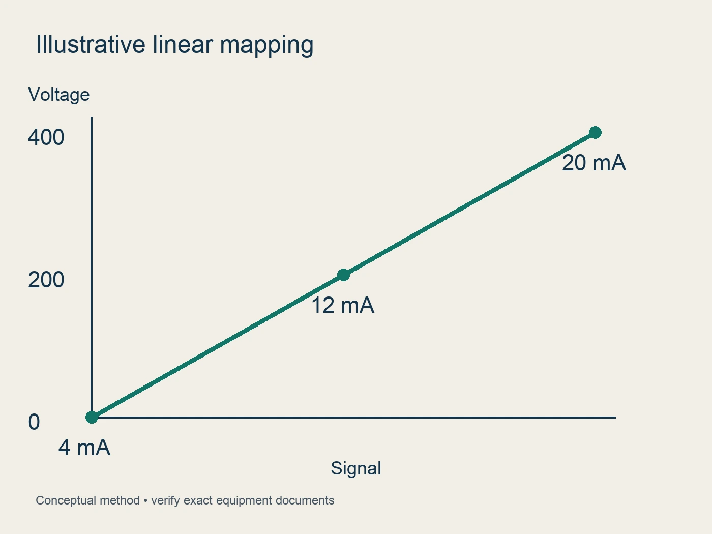
The following figures are invented teaching inputs, not VDT-20 or PLC specifications. Assume a hypothetical transducer represents 0–400 V AC with a 4–20 mA output. Assume a hypothetical receiving system delivers the signal in milliamperes. The engineering calculation becomes V = (mA − 4) × 400 / 16. The 16 mA quantity is the signal span, rather than its upper endpoint.
| Hypothetical received signal | Fraction of signal span | Calculated measured voltage |
|---|---|---|
| 4 mA | 0 | 0 V |
| 8 mA | 0.25 | 100 V |
| 12 mA | 0.50 | 200 V |
| 16 mA | 0.75 | 300 V |
| 20 mA | 1 | 400 V |
This example shows why subtracting the lower endpoint matters. Dividing the received current directly by 20 and multiplying by 400 would produce 80 V at 4 mA, even though the assumed transducer mapping assigns that signal to zero measured voltage. A correct-looking upper endpoint would hide the lower-end error.
If the PLC instead returns a raw integer, replace the current endpoints with the verified nominal raw endpoints; do not mix an integer raw value with milliamperes in the same formula. Testing several points is useful because an incorrect offset and an incorrect span produce different patterns. The table is an arithmetic reference, not an acceptance tolerance for a real assembly.
Keep validity separate from the displayed number
A scaled number and a valid measurement are separate outputs. Carry the channel diagnostic state alongside the engineering value. Define how the program handles a signal below its nominal range, above range, absent, stale or otherwise invalid. Use the module and transducer documentation to identify those states; there is no single fault code that applies to every analog input.
Avoid silently clamping every value to the nominal endpoints before diagnosis. Clamping might be useful for a particular display, but it can conceal a broken connection or an overrange condition. If a displayed value is limited, preserve the original value and diagnostic state for maintenance. Similarly, holding the last valid reading needs a visible stale indication and a defined application response.
Choose the response with the machine designer. A logging channel, a supervisory alarm and an input used in an interlock can require different treatment. This article does not define a safety function or certify the control logic. It provides a way to keep numerical conversion from concealing the receiving channel's health.
Document the unit on every engineering tag, trend and exported column. A bare value called voltage is ambiguous when the panel includes line voltage, transducer output voltage and control supply voltage. A meaningful tag description reduces the risk that future software changes connect the wrong signal to the right-looking scale.
Verify the chain in stages
Begin with a program calculation test using declared numerical inputs. This confirms arithmetic, data types, endpoint values and display formatting without claiming anything about the physical transducer. Then test the receiving channel with an appropriate signal source under an approved commissioning procedure. That checks the interface and the software chain, but still excludes the AC measurement stage.
Finally, verify the complete measurement chain using suitable reference equipment and a controlled test arrangement. Work on the electrical system only under the site's qualified-person procedures. Record the applied measured voltage, reference reading, transducer signal, PLC raw value, engineering result, diagnostic state and HMI result together. Keeping all stages visible makes a discrepancy easier to localize.
Set acceptance limits from the project requirements and the relevant accuracy documents. Do not copy a supplier-listed transducer accuracy into a total-system tolerance without considering the reference instrument, receiver, wiring effects and test conditions. Decimal places are a display choice; they do not establish measurement uncertainty.
At the lower and upper endpoints, compare the expected mapping with the observed chain. At intermediate points, look for systematic offset, span error, incorrect units or abrupt numerical steps. Record any filtering and acquisition timing that affects settling. A slowly updating display should not be confused with a wrong steady-state scale.

Keep a commissioning record that survives changes
The final record should identify the exact transducer configuration, receiving-module part number, channel mode, program revision and HMI tag. Attach the documents used to choose raw and engineering endpoints. Store the date, test equipment identity, procedure and acceptance criteria with the observations so another engineer can reproduce the interpretation later.
Repeat the relevant check when a transducer range, output option, input card or program endpoint changes. Replacing a module with a visually similar item is not sufficient evidence that its representation is unchanged. Even a correct physical signal can acquire a different numerical meaning after software or configuration work.
For procurement, ask RITOKS to confirm the selected VDT-20 measured range and output signal, then provide the receiving-channel documentation and the intended engineering range. Request available configuration evidence and output-loading information before finalizing the interface. Frequency response, isolation and load limits should remain open questions when the exact documents do not establish them.
The deliverable is a traceable mapping with explicit validity handling and recorded endpoint checks. It gives maintenance a defensible route from an AC measurement to a PLC number, while keeping device capability, total accuracy and application decisions tied to the actual ordered equipment.
Source notes
- Siemens. NORM_X: Normalize, S7-1200/S7-1500 instruction documentation. Retrieved 2026-09-30: https://docs.tia.siemens.cloud/r/en-us/v20/fbd-s7-1200-s7-1500/conversion-operations-s7-1200-s7-1500/norm_x-normalize-s7-1200-s7-1500
- RITOKS. VDT-20 DIN Rail AC Voltage Transducer. Retrieved 2026-09-30: https://ritoks.com/products/vdt-20-din-rail-ac-voltage-transducer/