
Radiatory modułów zasilających · Objaśnienie techniczne
Heatsinks in Rectifier and Power-Control Cabinets
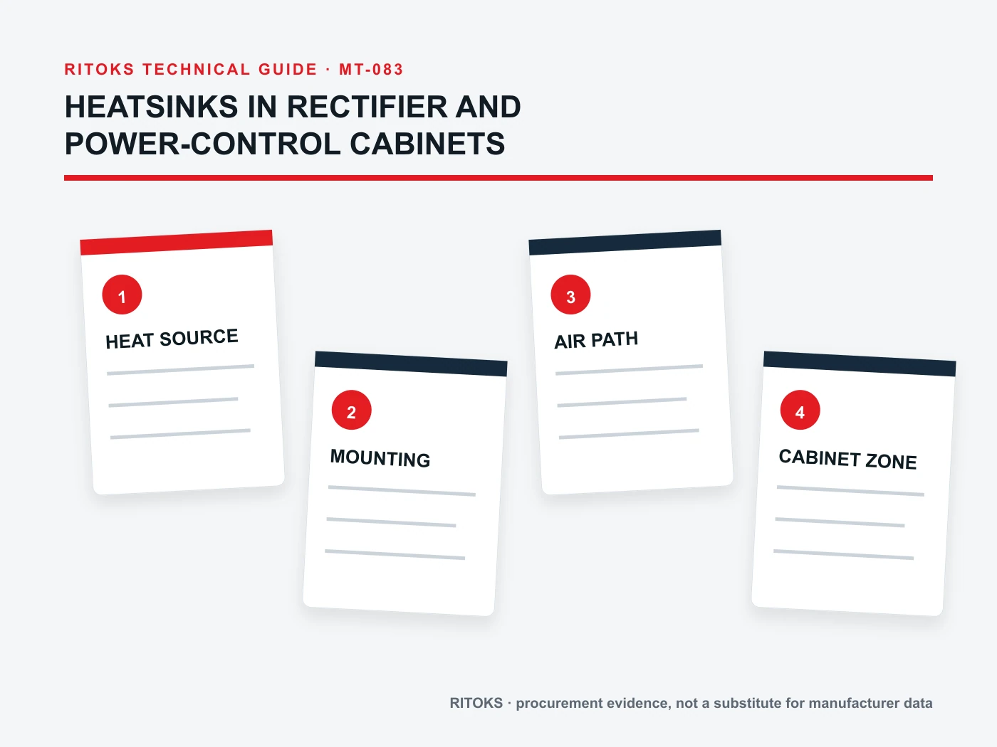
A heatsink in a rectifier or power-control cabinet is one part of a thermal path. Heat moves from the semiconductor junction through the module base and mounting interface, into the heatsink, and finally into cabinet air or an external cooling stream. If any link is poorly defined, a large-looking extrusion cannot guarantee acceptable device temperature.
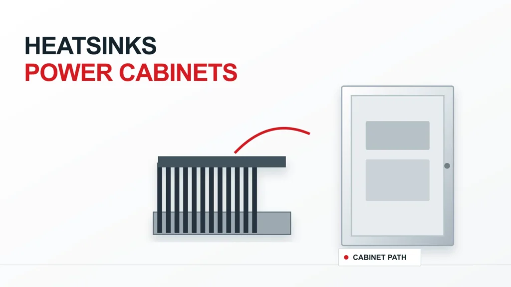
This application guide shows which enclosure and airflow conditions should be documented before choosing a power module heatsink. It does not size a sink for an unknown device, prescribe mounting torque or assert that a particular RITOKS module and heatsink are compatible. Those decisions require exact device and heatsink documents plus a project thermal calculation.
The Cabinet Changes the Heatsink Question
A heatsink tested in open air may behave differently when placed inside a crowded cabinet. Internal air temperature can rise above room ambient; neighboring modules can warm the inlet air; barriers and cable bundles can reduce circulation. Fan presence alone does not prove that useful airflow crosses the fins. The design team must define the air temperature and flow available at the actual sink position.
The electrical duty also affects heat generation. A rectifier module carrying pulsed current, an SCR controller with changing conduction angle and a continuously loaded power stage do not have the same loss profile. Start with the exact semiconductor operating case and loss data, then work outward through the interface and cabinet air path.
| Thermal link | Project question | Evidence needed |
|---|---|---|
| Semiconductor | What losses occur in each duty case? | Exact device data and operating calculation |
| Mounting interface | How is heat transferred to the sink? | Exact mounting and interface instructions |
| Heatsink | Which orientation and flow conditions apply? | Sink drawing and conditional performance data |
| Cabinet air | What temperature and movement reach the fins? | Enclosure thermal and airflow assessment |
| Środowisko | What ambient and contamination conditions matter? | Site and maintenance specification |
Start with Loss, Not Heatsink Size
The module's power loss is the heat the thermal path must remove. Obtain the exact device loss data for the expected current waveform, conduction pattern, switching behavior and duty. Avoid using a family maximum, a nominal load current or another application as a substitute. The resulting loss range should cover normal operation and any credible short-duration condition that the thermal design must withstand.
For a rectifier, source and DC-side behavior can change current waveform and conduction loss. For a controlled power stage, operating angle or switching sequence may matter. The thermal designer should calculate the cases that actually govern selection. Procurement can carry the calculation result and assumptions into the RFQ, but should not invent a loss figure to fill an empty field.
Define the Available Air Temperature
Cabinet air at the heatsink may be warmer than the external ambient. It can be affected by transformers, contactors, resistors, adjacent semiconductor modules and the enclosure's own solar or process exposure. Ask for a temperature basis at the intended mounting position, not only the room specification. If the value is uncertain, mark the thermal result provisional.
Consider whether the cabinet is sealed, filtered, ventilated or actively cooled. A sealed cabinet may need a different heat-rejection route from a cabinet with an engineered intake and exhaust. The heatsinks category can help identify candidate forms, while enclosure design determines the boundary condition in which they operate.
Map the Actual Air Path
For forced-air designs, show where air enters, how it crosses the fins and where it leaves. Include filters, guards, wiring ducts, neighboring equipment and the available pressure path. A fan rating measured without the cabinet restriction cannot prove the flow through the heatsink. Ask the responsible team to evaluate the fan and enclosure as a system.
For natural convection, document fin orientation and the free space above and below the sink. A horizontal or obstructed installation can differ materially from a published open-air test arrangement. The exact heatsink performance data must be read under conditions that resemble the intended mounting, with any mismatch called out for review.
Keep Hot-Air Recirculation Visible
Cabinets can recirculate exhaust air back into a module inlet. This raises the effective cooling-air temperature even when the fan is running. A layout drawing should show upstream heat sources, plenum boundaries and discharge direction. During commissioning, measurement locations should distinguish room temperature from the air actually entering the sink.
Do not assume that adding a larger fan will fix recirculation. It may change flow distribution without providing a cooler inlet. The correct response could involve ducting, rearranging equipment, separating air paths or changing the enclosure thermal strategy. The choice belongs to the cabinet designer after reviewing the whole heat path.
Review Interface and Mounting Details
Heat transfer between a semiconductor base and an extrusion depends on flatness, contact area, interface material, mounting pattern and applied force. Exact module instructions may define these details. Do not copy a torque or compound thickness from a different device. Verify that the proposed heatsink footprint, hole pattern and surface condition are compatible with the quoted module.
Record who supplies the interface material, fasteners and any insulating layer. These items can affect thermal performance and electrical safety. A complete assembly drawing should show the intended stack. If an alternative module or sink is proposed, check the interface again rather than assuming that matching outside dimensions prove compatibility.
Consider the Cabinet Layout and Service Path
Leave space for airflow, electrical clearance, cable routing and maintenance access around the heatsink. A tightly packed layout may make a nominally adequate thermal design difficult to install or clean. Ask the panel builder to compare the sink envelope and fin direction with the real cabinet drawing before ordering hardware.
Filters, lint and process dust can increase flow resistance over time. If the cooling concept depends on a clean filter or unobstructed fins, define inspection and maintenance expectations. A cabinet exposed to contaminants may need a different air path or enclosure strategy. Maintenance should be part of the design input, not an afterthought left to the operator.
Compare Natural and Forced-Air Options
Natural convection can avoid a fan dependency, but it requires a suitable heat-rejection area, orientation and air space. Forced air can move more heat through a compact assembly under defined flow conditions, but it adds fan power, control, filtration and a failure mode. Neither method should be selected from a product photograph or a generic preference for simplicity.
Compare the proposed aluminum power module heatsink oraz forced-air heatsink family as candidate forms only. Confirm exact dimensions, compatible module mounting and performance conditions in current documentation before treating either as suitable for the cabinet.
What to Put in the Heatsink RFQ
Provide the exact power module identity, calculated loss cases, allowed temperature limits from its datasheet, interface requirements, cabinet air temperature, available airflow or natural-convection arrangement, mounting orientation and mechanical envelope. Include the enclosure drawing and nearby heat sources. If a fan is specified, include the installed airflow basis rather than a free-air nameplate value alone.
Ask the supplier for an exact heatsink drawing, mounting information, conditional thermal performance data and any included fan or accessory details. Require them to state assumptions and missing inputs. This turns a visually similar assortment of extrusions into a reviewable engineering comparison.
Verify with the Complete Assembly
A calculation is useful only when its assumptions match the installed assembly. During prototype or commissioning review, measure the relevant temperatures under defined load and ambient conditions, and record fan operation or airflow where applicable. Compare the results with the semiconductor limits using the exact measurement method approved by the design team.
Do not use one cool external sink point as proof that an internal junction is within limit. The thermal path calculation connects measurable locations to device temperature. Keep test conditions, sensor locations and document revisions with the results so later cabinet changes can be assessed against the original basis.
Common Cabinet Thermal Errors
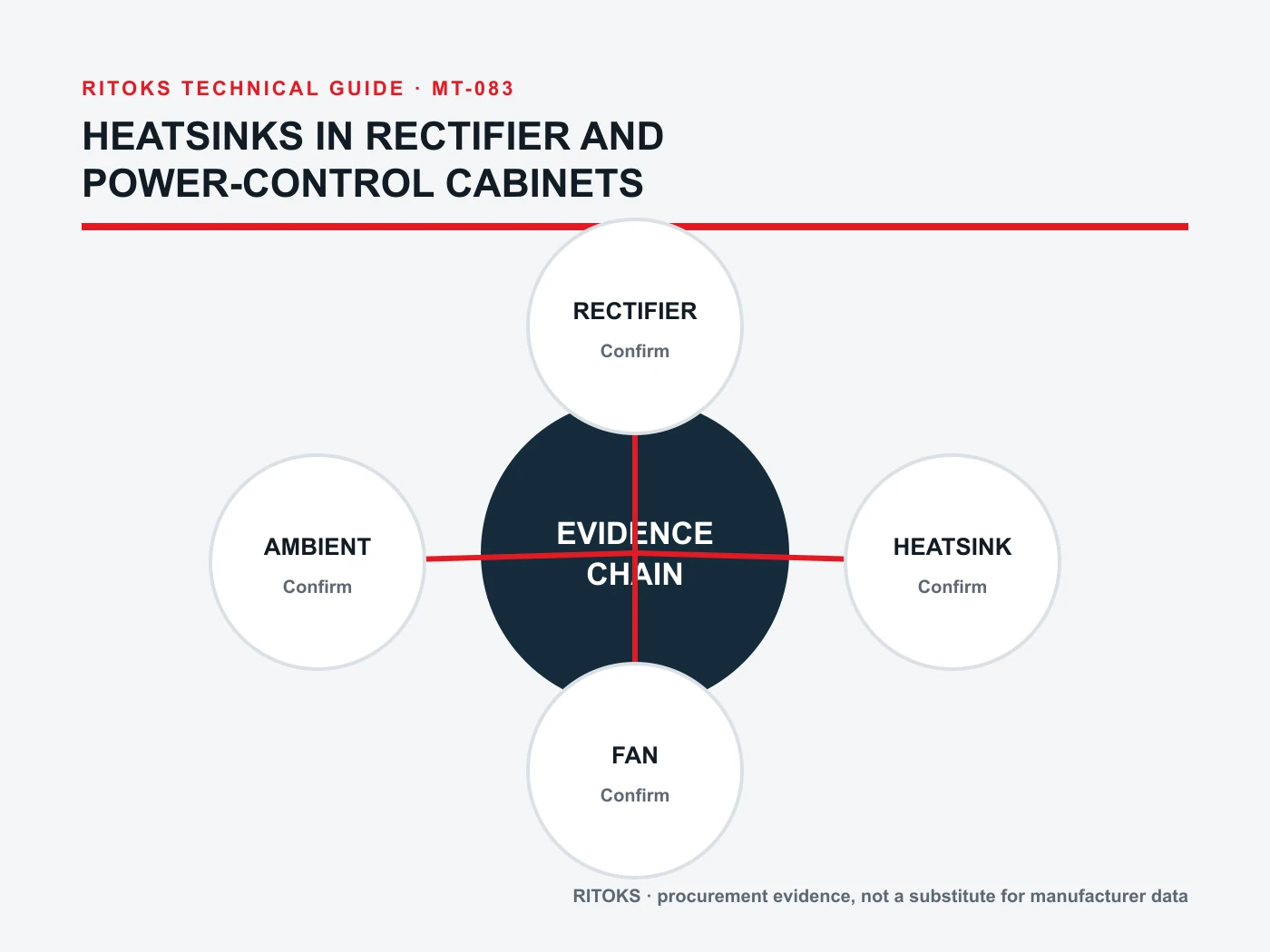
Common errors include using room ambient as heatsink inlet temperature, assuming a fan's free-air rating reaches the fins, ignoring recirculation, and copying open-air thermal data into a sealed cabinet. Another is comparing heatsinks by size while overlooking interface quality and semiconductor loss. Each error breaks a different part of the same junction-to-air chain.
Resolve the uncertain link rather than adding an unexplained safety factor to the last spreadsheet cell. If loss is uncertain, obtain better device data. If airflow is uncertain, examine the cabinet path. If the interface is uncertain, inspect the mounting documentation. This makes the design review auditable and keeps the RFQ tied to actual conditions.
Questions Before Approval
- Which exact semiconductor and loss cases govern the thermal design?
- What air temperature and flow reach the heatsink in the installed cabinet?
- Do the published sink conditions match orientation and available clearance?
- Is the mounting interface supported by exact module and sink instructions?
- How will fan or filter degradation be detected and maintained?
- What prototype measurements will confirm the calculation?
Send the module, cabinet and duty record through the Strona z zapytaniami dotyczącymi RITOKS for an exact candidate. Keep unresolved thermal calculations with the responsible engineer. The purchased part should be traceable to the conditions under which its cooling role was evaluated.