
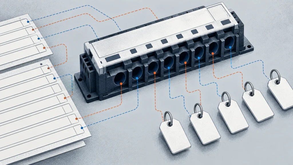
Building a Reliable Channel Map for Branch Current Monitoring
Trace each branch-current reading from circuit and sensor through module input and data point to its platform tag, preserving change history.

Trace each branch-current reading from circuit and sensor through module input and data point to its platform tag, preserving change history.

Separate signed measurement, permitted reverse exposure and output indication before selecting a transducer for a circuit that may reverse current.

Preserve as-found evidence and define the reference, mapping, uncertainty and response endpoint before accepting a DC current transducer.
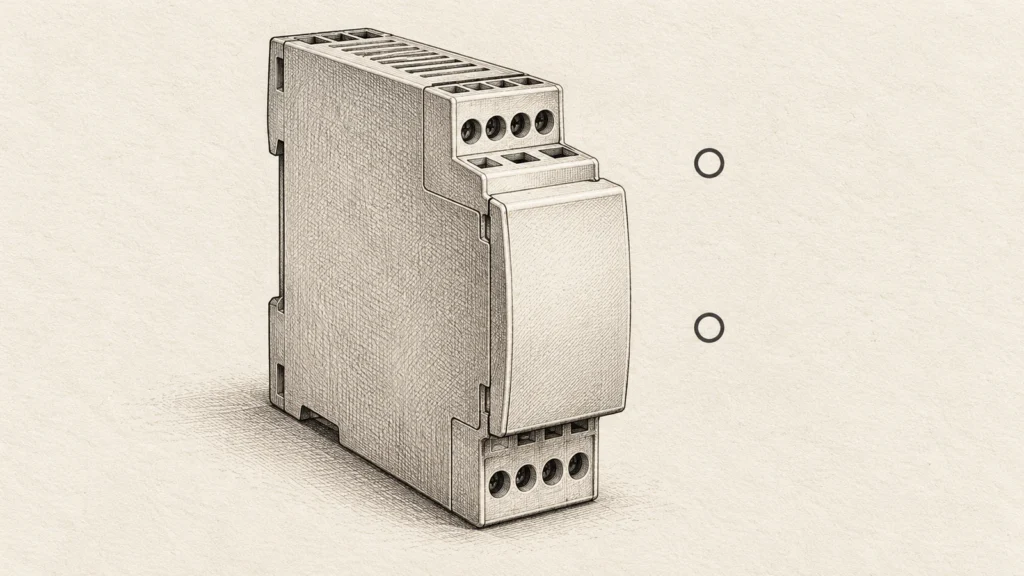
Name both measured nodes and the actual system topology before choosing the input range, output and supply configuration.

Voltage transducer PLC scaling converts the receiving channel’s raw value into the voltage represented by the selected transducer output. A reliable result needs two endpoint pairs: the PLC values assigned to the electrical signal endpoints, and the measured-voltage endpoints assigned to the transducer.
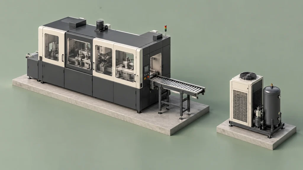
Define main, dedicated and shared loads, then align energy and production records before comparing energy per unit of output.
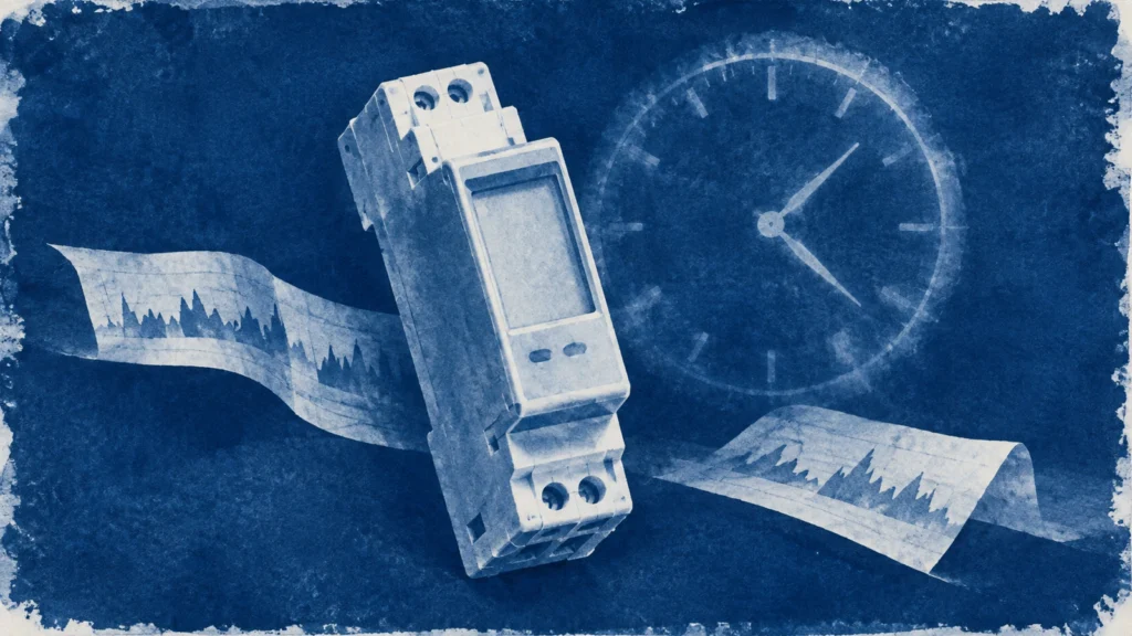
Verify retained energy fields, settings and any supported clock or logs separately, then distinguish meter recovery from monitoring-history continuity.

Check time intervals, register meanings, nonoverlapping coverage and scaling before assigning a main/submeter residual to loss or meter failure.

A kW reading describes power at a moment or over a defined demand interval; a kWh reading describes energy accumulated over time. Learn how to read both without mixing them up.
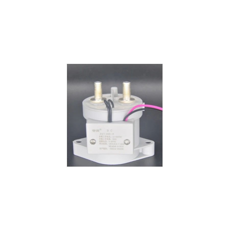
Select a high-voltage DC contactor by separating bus voltage, main-contact duty, coil supply, auxiliary contacts and exact-model switching evidence.