
DC Fuse Links · Technical Explainer
Battery Fuse Coordination with Contactors and DC Bus Components
Quick answer
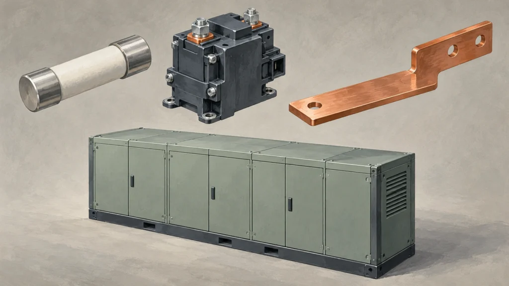
A battery fuse and contactor are not coordinated merely because their rated currents match. Review the actual DC fault conditions, the fuse's interruption range and clearing characteristics, and the contactor's ability to carry or interrupt the relevant current. Include the busbars, joints and other series components in the protection assessment.
The procurement deliverable should be an evidence matrix tied to exact order codes and an approved system configuration. It must distinguish peak let-through current, total clearing I²t, time-current behavior and operating sequence. Missing component withstand information is an unresolved coordination issue, not a value that can be filled in from nominal current.
This article organizes engineering and supplier evidence. It does not approve a particular combination or provide a battery fault-test procedure. Fault studies, control sequencing and validation belong to qualified professionals working with the component and system manufacturers.
Start with the protected path, not the component catalogue
Draw the actual current path from the relevant battery source through its protection, switching and distribution components. Identify the fault locations being considered. A fault in a rack, on a common bus or near the converter may expose different components to different source contributions.
Mersen's EES Application Guide, in its fault-current sections, illustrates why the location and contribution of multiple racks matter. A single maximum current assigned to every fuse position can conceal the differences between what flows at the fault and what flows through an individual protective device.
Record the approved topology and relevant operating states. Parallel sources, connected converters and alternative system states must be considered where applicable, rather than omitted because the purchasing list contains only one battery fuse. The study should establish the current seen by each component being assessed.
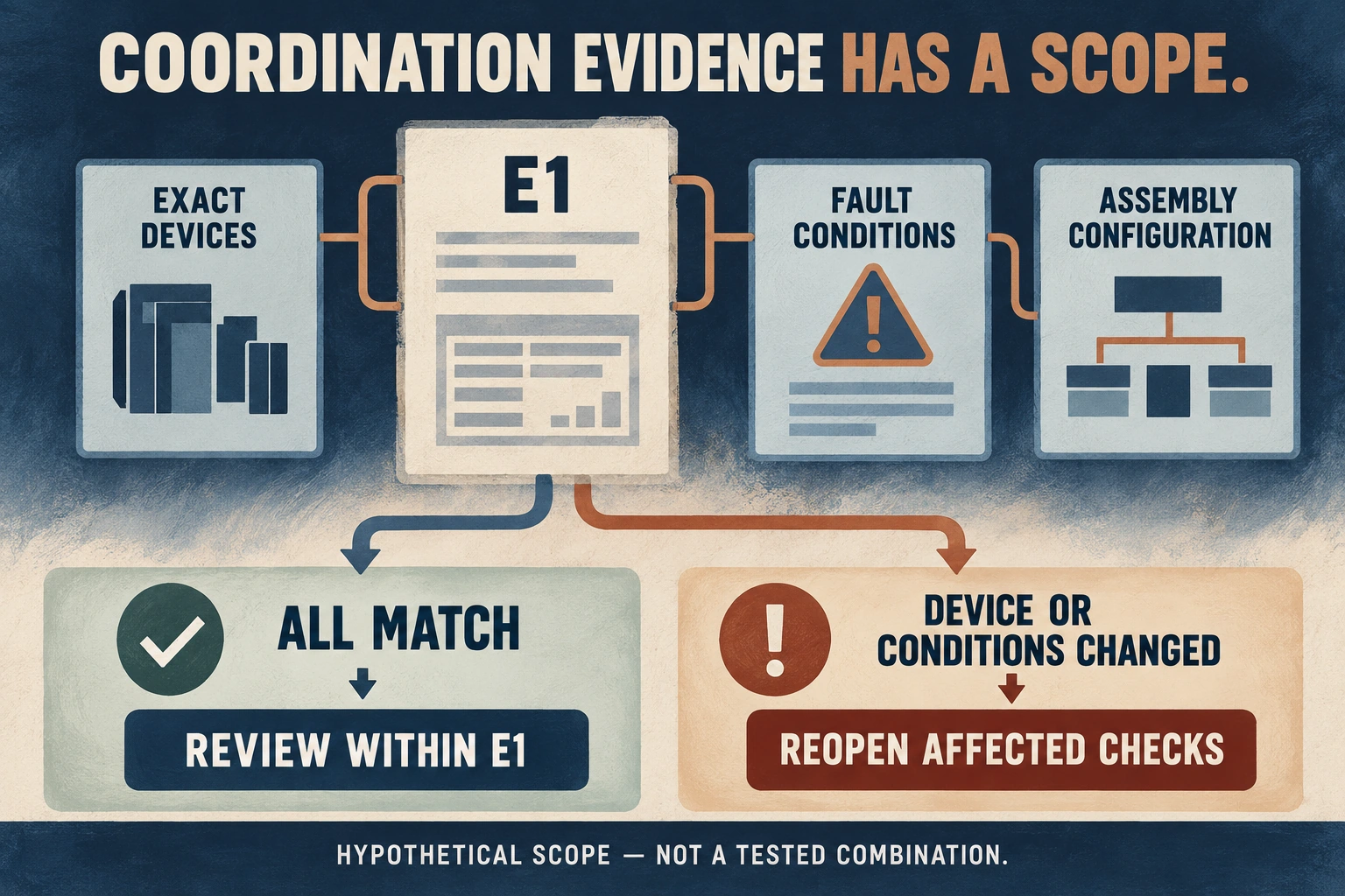
Include the physical arrangement in the configuration identity. A changed bus route, connection or source population can change the electrical conditions. Coordination evidence for one assembly should not silently become approval for a revised layout with the same component names.
Define the DC conditions behind every rating
Obtain the maximum system voltage and the relevant prospective fault-current envelope from the system study. Record the time-dependent current and circuit conditions needed by the component suppliers, including the applicable DC time constant or other stated test conditions.
Mersen's guide defines fuse interrupting and minimum breaking capabilities with reference to specified DC voltage and time constant. Both ends of the supported interruption range matter. A high maximum interrupting rating does not show that every lower overcurrent is cleared by that fuse under the application's conditions.
Sensata's 2025 EV protection white paper shows how circuit inductance affects the development of a battery fault and the current-time duty seen by a contactor. Its example concerns an actively triggered pyrotechnic protection system. Use the underlying need to characterize the fault, not its device performance or trigger timeline as a substitute for a conventional fuse assessment.
Keep continuous-duty selection separate. Ambient conditions, mounting and normal cycling remain important to fuse and contactor selection, but satisfying them does not establish short-circuit protection. The coordination record needs both the normal operating basis and the fault basis.
Ask for matched fuse and component evidence
Request data for the exact fuse order code, not merely a family brochure. Identify whether a supplied time-current curve represents melting or total clearing and which conditions accompany the published data.
For protection of downstream components during interruption, do not use pre-arcing I²t as though it represented the whole event. The current does not necessarily stop at the moment the fuse element melts. The total clearing quantity includes the interruption process that follows.
Mersen's current-limitation explanation distinguishes peak let-through current from clearing I²t and cautions that DC results depend on voltage, available fault current and time constant. Do not insert an AC peak-current conversion or an AC test value into a battery coordination record without valid application evidence.
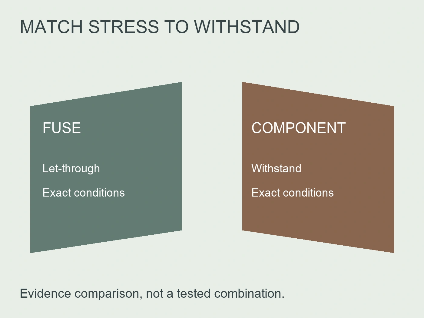
The following original matrix establishes what needs to be matched. It is not a universal calculation rule or an approved component pairing.
| Coordination item | Fuse evidence to request | Protected-component evidence to request |
|---|---|---|
| Supported interruption range | Minimum and maximum breaking information under relevant DC conditions | Duty assigned to the contactor or other protection outside that range |
| Peak current during clearing | Applicable peak let-through data and its conditions | Relevant peak-current or mechanical withstand evidence |
| Thermal current-time exposure | Total clearing I²t or appropriate clearing-time evidence | Compatible short-time thermal limits and their stated conditions |
| Contactor behavior during the event | Fuse operation across the studied current range | Closed-state withstand, permitted interruption duty and operating behavior |
| Bus and connection protection | Current waveform or limits applicable to each location | Evidence for the installed bus, joints, terminals and support arrangement |
| Normal operating duty | Current-cycling and environmental selection information | Continuous current and operating-duty requirements |
Do not force every component limit into I²t. A manufacturer may specify a current-time envelope, a peak limit or validated conditions instead. Ask how the available evidence should be compared and whether further analysis or testing is necessary.
Cover the lower-current region as well as the severe fault
A proposal can look convincing at the highest prospective current while leaving a gap at lower overcurrents. Establish which device is expected to interrupt each part of the studied range, and whether that expectation is supported by its actual capability.
The contactor coordination section of Mersen's guide requires attention to the fuse's minimum breaking capability, the contactor's interruption ability below that region and the time available before contactor damage. This is a coverage review, not a recommendation that an ordinary contactor can interrupt any battery fault.
Ask the system supplier to identify the transition between the intended duties. A table saying “contactor for overload, fuse for short circuit” is incomplete if no evidence establishes where the boundary lies and whether both devices can fulfil their duties around it.
Do not infer lower-current coverage from a utilization-category label alone. Obtain the exact product information and relevant conditions. Where a contribution is current-limited or varies with the battery state, retain that behavior in the assessment instead of treating the highest available current as the only meaningful case.
Review the contactor sequence, not only its closed-state limit
The contactor may be closed when the fault begins, and its behavior during clearing is part of the system design. Record the relevant command, control-power and operating-state assumptions. Do not approve a combination solely by comparing a fuse curve with a static current rating.
Identify whether the contactor is intended to remain closed during a particular fault interval or interrupt within its supported duty. The supplier must substantiate that behavior and the associated limits. A control command does not establish what the physical contacts do, and a theoretical fuse clearing time does not establish the complete sequence.
Sensata's active-protection example illustrates that protection timing and contactor withstand must be assessed together. It does not provide a generic delay setting for a thermal fuse or establish the capabilities of another manufacturer's contactor.
Avoid prescribing a fixed hold-closed duration or instructing an operator to override a protection command. The approved sequence must address the actual fault envelope, component information and system safety requirements. If that sequence has not been reviewed, mark the combination conditional.
Include the busbar and every vulnerable series component
A coordinated fuse-contactor pair does not automatically protect the entire DC distribution path. Review bus sections, joints, terminals, shunts, connectors and cables according to their position and the relevant fault exposure.
Busbar continuous ampacity does not establish short-circuit withstand. Request evidence for the installed arrangement, including dimensions, connections and supports where they affect the manufacturer's stated limits. A material description or a copper cross-section alone is not an assembly approval.
Peak current and current-time exposure address different aspects of the duty. Passing one comparison should not hide a missing limit for the other. A strong bus section may also contain a connection or component with a different supported duty, so list the relevant items rather than assigning the bus's rating to the whole path.
Where evidence relates to an assembly test, identify the actual assembly covered. Where it is a component limit, record its conditions and the basis for applying it to the installation. Do not convert either into a larger fault rating for the complete cabinet without the required substantiation.
Review the complete evidence package before placing the order
Use a common review record so the battery-system supplier, fuse supplier and contactor supplier can see the same assumptions. Different suppliers may otherwise answer different questions while every quotation appears to say “suitable.”
| Review gate | Required conclusion | Condition that keeps the proposal unresolved |
|---|---|---|
| Fault envelope | Relevant locations, sources and DC conditions established | Only a generic maximum current supplied |
| Exact components | Order codes and revisions fixed | Family data used without identifying the selected configuration |
| Duty coverage | No unsupported region between device duties | Fuse minimum breaking or contactor interruption evidence missing |
| Fault exposure | Applicable peak and current-time comparisons supported | Only continuous-current ratings compared |
| Operating sequence | Physical switching behavior and limits addressed | Sequence assumed from control logic alone |
| Assembly scope | Bus, joints and series components included | Approval limited to one pair but reported for the cabinet |
| Validation and change control | Required substantiation and configuration boundaries recorded | Untested substitutions accepted as equivalent |
These gates create an engineering handoff, not a claim that a checklist alone validates the system. The responsible parties should decide which comparisons are sufficient and which need additional manufacturer review or representative validation.
Record whether the objective is damage prevention, safe interruption, permitted post-fault condition or another agreed requirement. Do not use the word “survives” without saying what condition is acceptable after the event. Safe interruption is not automatically a promise that every component can immediately return to service.
Compare a filled stress record with two different limits
Consider a hypothetical coordination submission C1 for one defined DC fault location and one fixed assembly configuration. Its fictional manufacturer evidence supplies a fuse peak let-through value of 4.5 kA, pre-arcing I²t of 30000 A²s and total clearing I²t of 46000 A²s. The fictional contactor evidence supplies a compatible peak limit of 6 kA and thermal limit of 42000 A²s for the same assessed duty and stated comparison method. These are teaching values, not RITOKS, Mersen or Sensata specifications or a recommended component combination.
The peak comparison is favorable on its stated basis: 4.5 kA is below 6 kA. The thermal comparison is not: 46000 A²s exceeds 42000 A²s. Substituting the 30000 A²s pre-arcing value would reverse the apparent answer, but it would omit part of the event. The filled C1 record therefore reads "peak comparison within supplied limit; total-clearing thermal comparison outside supplied limit." It cannot be accepted simply because one number passes or because the fuse and contactor share a nominal current.
Suppose the bus assembly in this fictional record has a compatible peak limit of 8 kA but no supplied thermal limit or accepted current-time assessment. Its peak row can be recorded separately, while its thermal row remains unresolved. The contactor's 42000 A²s limit cannot be assigned to the bus, its supports or a joint. A complete pair comparison would not close that missing assembly evidence, and a public busbar ampacity would answer a different normal-service question.
Next consider a fictional substitute F2 whose submitted total clearing I²t is 38000 A²s but whose peak let-through is 6.5 kA under the same comparison conditions. Its thermal comparison against the contactor becomes favorable, while its peak comparison becomes unfavorable. F2 is not automatically a better protective choice: it trades one compatible stress comparison for another incompatible one. No relation between these two values is calculated here, and neither is inferred from rated current. They must be distinct pieces of applicable manufacturer evidence.
The timing review also remains independent. If a control record merely says "open contactor on fault," neither C1 nor F2 establishes that the contactor can interrupt the current at its actual opening instant. Closed-state limits do not supply that opening duty. The system owner must establish the supported physical sequence and failure assumptions rather than add a guessed delay to make either stress record appear acceptable. This example provides no override instruction or fault-test method.
The procurement result is thus more precise than "coordination failed" or "higher-rated fuse required." C1 needs resolution of the contactor thermal comparison and bus thermal evidence; F2 changes the contactor peak question while leaving the operating sequence and assembly scope open. A supplier can address those specific gaps with appropriate evidence or a revised design. The designer must still decide the acceptable post-event condition and validate the whole configuration; these fictional comparisons cannot approve an actual battery cabinet.
Turn a battery-fuse inquiry into a coordination request
RITOKS lists DNESS2-S8L battery DC fuse links as a sourcing destination. Request the selected configuration's current technical data and submit the actual system voltage, fault study, operating duty and protected-component information with the inquiry.
The public product page is not evidence that a particular contactor or bus assembly is coordinated with that fuse. It does not replace exact peak let-through, total clearing and component-withstand information for the proposed combination. Do not derive those values from the page's rated current or interrupting rating.
A useful supplier response identifies supported conditions, missing information and the next required review. A response containing only a recommended ampere rating should not close the coordination task.
Referências
- Mersen. (n.d.). EES Application Guide. Relevant complete sections: prospective faults, interruption range and contactor coordination, printed pages 9–12. Retrieved October 2, 2026.
- Mersen. (n.d.). Reducing arc energies with fuses. Relevant sections: current limitation, peak let-through, clearing I²t and DC application caveats. Retrieved October 2, 2026.
- Sensata Technologies. (2025). Maximizing circuit protection for enhanced EV safety. Four-page active-protection example; qualitative fault dynamics and contactor timing only, not a conventional-fuse pairing approval.