
Current Transformers · Technical Explainer
A 20 mA CT Output Is Not a 4–20 mA Signal: Interface Differences

Quick answer
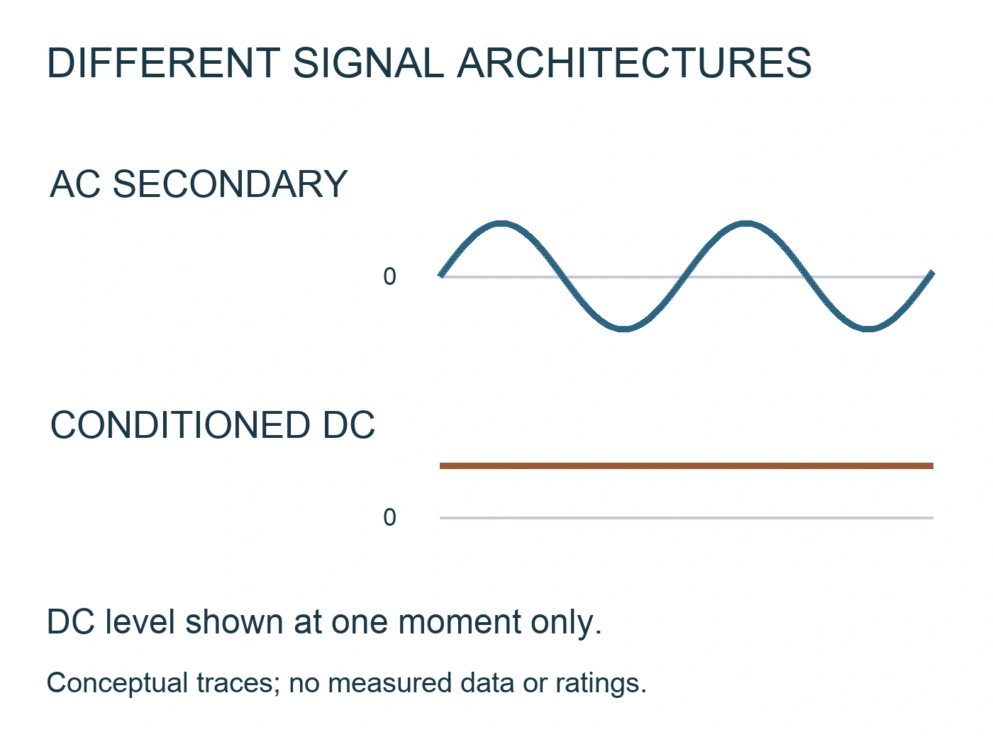
A current transformer's rated 20 mA AC secondary output is not the same interface as a transmitter's 4–20 mA DC output. The first describes a transformer signal under specified measurement conditions; the second describes a conditioned current signal with a defined transfer function. Matching the number 20 does not establish electrical compatibility.
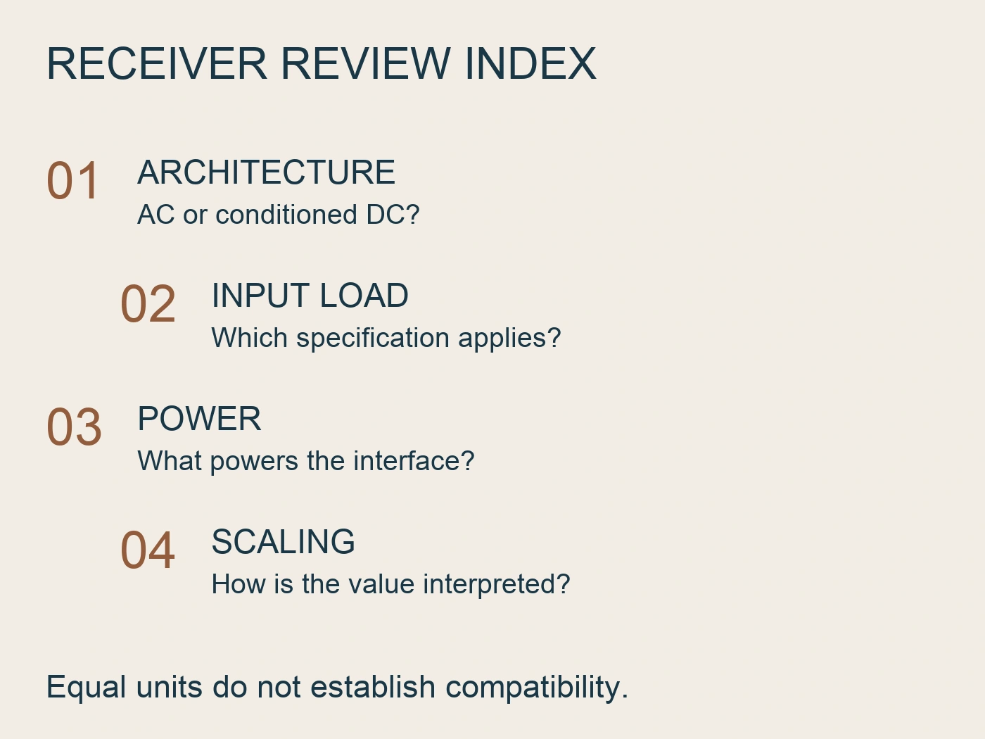
Before ordering, compare output waveform, signal range, burden or load, supply requirements and receiving-input specification. Do not connect a transformer directly to a process-current input merely because both documents mention milliamps. This guide helps buyers prepare an interface comparison; circuit design, installation and testing require the exact component documentation and qualified engineering review. For a voltage transducer with a process-current output, see scaling the signal in a PLC.
Read the unit together with the signal description
The unit mA states current magnitude, not how the current represents the measured quantity. A purchasing line that says only “20 mA output” omits whether the signal is AC or DC, whether 20 mA is a rated secondary value or an upper signal endpoint, and what load conditions apply. Those omissions can change the entire receiving circuit.
RITOKS explicitly lists the Transformator de curent miniatural GTA20L with a 20 mA AC rated output and model-dependent primary current and ratio. Its specification table distinguishes performance under different burden conditions. That is different from a declaration that the product produces a standard 4–20 mA DC process signal.
Cele publicate Transductor de curent alternativ VDT-26 separates its AC input options from selectable output types and an auxiliary supply. Its current-output option is described as 4–20 mA DC. The family also lists other output options; a buyer must identify the chosen configuration rather than treating the entire family as one output interface.
Write the full signal description in the comparison sheet. “Rated secondary: 20 mA AC” and “selected output: 4–20 mA DC” make the mismatch visible without needing to inspect a wiring sketch. Keep those descriptions alongside the exact model reference, because the primary range and complete order designation also matter.
Separate the transformer signal from the processed value
A transformer interface and a process-current interface place different tasks on the receiving electronics. The transformer signal needs a measurement circuit suited to that component and its burden conditions. A conditioned output presents a defined signal representation that the receiving system interprets using an agreed scale. Neither arrangement can be selected from output magnitude alone.
Talema's AC-series documentation pairs a turns ratio with a specified burden resistance. It provides a concrete manufacturer example of why burden belongs in a CT interface specification. Its values apply to that Talema series and should not be copied into a GTA20L design (Talema, n.d.).
LEM's AT-B420L datasheet documents a different example: an AC current transducer with a loop-powered 4–20 mA output proportional to primary RMS current. This is evidence of one defined conversion arrangement, not proof that every transducer uses the same processing method or supply arrangement (LEM, 2022).
| Interface question | Rated 20 mA AC CT secondary | Selected 4–20 mA DC output |
|---|---|---|
| What does the label identify? | A secondary current rating for the specified transformer | A conditioned signal interval for the selected transmitter |
| What must the receiver understand? | The CT signal and its measurement conditions | The output transfer function and corresponding engineering scale |
| Which load information matters? | Permitted burden and model-specific measurement performance | Permitted output load and supply conditions |
| What is still unspecified by the number? | Primary range, waveform conditions and input-circuit requirements | Measured quantity, scaling, power arrangement and fault behavior |
| Can the other interface be assumed compatible? | No, not from a shared milliamp value | No, not without the source and receiver specifications |
This comparison distinguishes document fields. It is not a circuit schematic or a recommendation for a particular resistor, converter or controller input.
Ask what the reported current represents
For a transformer, obtain the primary-to-secondary relationship and the conditions under which its accuracy and range are stated. Keep the chosen primary range separate from the secondary rating. Two models may share a rated secondary value while representing different primary currents; the receiver cannot resolve that difference from the output label alone.
For a transmitter, ask what input quantity the output represents. Is the specified output related to RMS current, another processed quantity or a configurable range? Request the exact declaration instead of assuming that all devices described as Transductoare de curent alternativ report the same measurement. The LEM example illustrates one documented RMS implementation, not a rule for VDT-26.
Also distinguish a defined signal endpoint from fault indication. A nominal scale does not establish how an instrument behaves during a broken signal path, an overload, loss of supply or an internal fault. Those behaviors require device and receiver documentation. Do not assign a universal fault current or claim that one low reading proves a particular failure.
The procurement record should make the intended interpretation explicit. “Controller displays load current over the agreed measuring range” is incomplete unless the source transfer function and controller scaling are both identified. Record the input quantity, the selected source range and the display conversion as separate items that can be checked against each other.
Check power and load without borrowing another device's values
The term current output does not identify who supplies power to the signal arrangement. A transmitter may use an auxiliary supply or a loop-powered arrangement. The receiver may receive a signal only or may supply the signal generator, depending on its design. Obtain the actual input and output descriptions before deciding how the interface works.
Phoenix Contact's signal-conditioning guidance distinguishes passive inputs that receive a signal from active inputs that also supply the signal generator. It further explains that signal conversion and isolation are separate functions available in different arrangements. Those distinctions are useful selection questions, not a wiring authorization for the products discussed here (Phoenix Contact, n.d.).
For a CT, ask whether the required burden is already incorporated or belongs in the receiving circuit. Check the relevant component data and input specification rather than adding a resistor from an unrelated example. Do not treat a burden value quoted for one accuracy condition as permission for every primary-current range or every receiving device.
For a conditioned output, request the permitted load at the intended supply conditions. Include the receiver and any intervening equipment in the interface review. A supplier's statement that an output is “standard” does not document the actual load capability, supply allowance or terminal allocation of the selected version.
Do not copy the supply or load limits from the LEM, Talema or Phoenix examples into a RITOKS quotation. They establish why those fields are needed. The exact GTA20L, VDT-26 and receiving-equipment documents must provide the values used in the real design.
Compare the receiving-input specification line by line
Start with the input manual, not the controller's general description. A product sold as a current-input controller can have several distinct input options. Record the exact channel configuration and the selected measurement mode, then compare them with the proposed source.
| Câmpul de recenzie | Source information to request | Receiver information to request |
|---|---|---|
| Signal form | AC secondary or conditioned DC output | Accepted waveform and input mode |
| Measuring scale | Exact primary range and output relationship | Selected engineering-unit scaling |
| Load conditions | CT burden or output load declaration | Input burden or impedance and any additional equipment |
| Power arrangement | Auxiliary supply or documented loop-power requirement | Whether the input provides power or only receives a signal |
| Signal processing | Defined measured quantity and response information | Sampling, processing and display requirements |
| Limits and abnormal states | Applicable limits and documented output behavior | Input limits and interpretation of unavailable or abnormal data |
| Connection identity | Exact source version and terminal drawing | Exact channel reference and terminal drawing |
An unanswered field should remain visible. Do not convert “not stated” into “compatible” because the other fields match. Identify which supplier or engineer must provide the missing information and what document would resolve it. This creates an actionable request rather than a vague rejection.
If an interface block is proposed, review both sides independently. Its input must match the source; its output must match the receiver. A generic signal conditioner does not necessarily accept a small AC CT secondary, perform the needed processing and deliver the required DC signal. Request the exact function and applicable limits of the proposed block.
Work through a conditional replacement example
Suppose a buyer is replacing a measurement assembly and receives a proposal listing “20 mA CT.” The existing controller schedule says “4–20 mA current input.” No actual installation or measured result is assumed in this example.
The first review asks the supplier whether the proposed source is a rated AC transformer secondary or a conditioned DC signal. If its data confirms the former, the shared number is no longer a reason to accept direct connection. The reviewer records a mismatch between signal forms and obtains the controller's exact input specification.
The supplier may then propose a signal-conversion assembly. That proposal should identify the complete input range, burden conditions, processing function, power arrangement and output limits. The designer compares those declarations with the controller requirements and decides whether the proposed assembly is suitable. A converter title alone does not close the issue.
Alternatively, the buyer may source a transmitter with a documented output that matches the controller. The selected measuring range and interpretation still need review. Matching 4–20 mA labels establishes a candidate interface, not approval of the entire measurement system, its installation or its accuracy under every condition.
Record the outcome against the exact ordered references. If either the source model or the receiver channel changes, reopen the relevant comparison rather than assuming that the earlier decision applies to the replacement configuration.
Prepare a precise RFQ
For a GTA20L enquiry, identify the primary measuring range and request the model-specific secondary, burden and performance documentation needed by the receiving-circuit designer. For VDT-26, identify the required AC input option, selected output and auxiliary supply, then request the exact interface and terminal documentation.
Keep the two product families separate in the RFQ. Do not offer them as interchangeable alternatives based only on their milliamp descriptions. Supply the receiving-input reference and describe the measurement result the project needs, so the supplier can address actual missing fields rather than guessing the signal architecture.
Întrebări frecvente
Does 20 mA AC mean a standard 4–20 mA output?
No. AC secondary rating and conditioned DC signal interval describe different interfaces. Read the waveform, range and load conditions, then compare the source with the exact receiving input.
Does a 4–20 mA transducer always need a separate supply?
No universal arrangement follows from that output label. Check whether the selected product uses an auxiliary supply or loop power, and how the receiving input participates. The VDT-26 family and the LEM example describe different supply arrangements.
Can I choose a converter by its output label alone?
No. Both its input and output must match the surrounding equipment. Ask whether it accepts the actual CT signal and performs the required measurement conversion, then verify its limits and power requirements.
Can another CT with the same secondary rating replace the original?
Not automatically. Compare primary range, ratio, burden conditions, performance documentation and receiving-circuit requirements. Shared secondary magnitude does not establish equivalent measurement behavior.
Referințe
- Talema. (n.d.). AC series: Low cost current transformer. https://talema.com/products/low-cost-current-transformers-ac/
- LEM. (2022, November 9). AC current transducer AT-B420L, version 11. https://www.lem.com/sites/default/files/products_datasheets/at-b420l.pdf
- Phoenix Contact. (n.d.). Conditioning and protection of digital and analog process signals. https://www.phoenixcontact.com/en-ch/technologies/industrial-signal-processing/digital-and-analog-signal-conditioning