
Power Distribution Components · Technical Explainer
Will a 24V Power Supply Ride Through a Brief AC Interruption?
Quick answer
A 24V power supply can support its load during a brief input interruption only within its documented hold-up conditions. The relevant question is whether the voltage at each critical device stays within that device's permitted range for the required interval, at the actual load and input conditions. A nominal 24V output label does not answer that question.
Compare the exact power supply's hold-up data with the PLC and other critical loads' supply requirements. Include wiring voltage drop, load state and the interruption being evaluated. Do not assume that an ordinary DIN-rail supply includes a UPS function or that one typical catalogue time guarantees every installation.
If the selected supply has no verified hold-up data, treat ride-through as unverified. Request the missing information before promising uninterrupted control operation to the machine customer.
Define what must remain operational
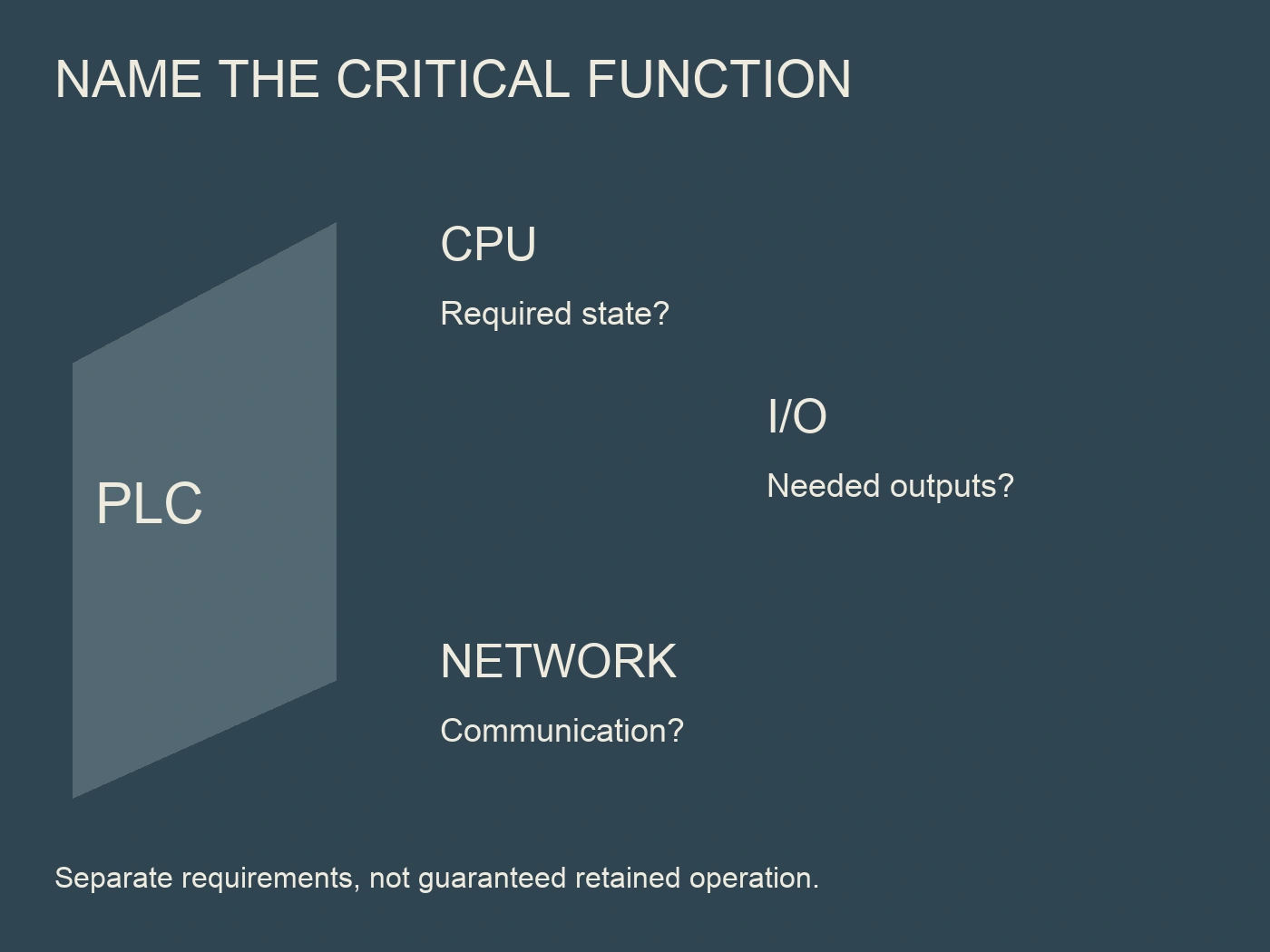
“The PLC stayed on” is narrower than “the control system continued functioning.” A system may include the CPU, remote I/O, network equipment, sensors, contactor coils and other loads with different supply requirements. Identify the critical functions rather than evaluate only one enclosure label.
| System question | Information required | Common incomplete answer |
|---|---|---|
| Which functions must continue? | Critical device and function list | “All devices are 24V” |
| How long is the interruption? | Defined event duration and waveform evidence | “It is only a short dip” |
| What output support is documented? | Exact supply hold-up data and conditions | A nominal power rating |
| What voltage can each load tolerate? | Device supply limits and applicable behavior | The supply's DC-OK lamp |
| What is present at the device terminals? | Wiring and applicable voltage-drop review | Supply-terminal voltage alone |
| How does the system recover? | Device/controller restart requirements | “It comes back eventually” |
The list should match the application. A system that requires orderly shutdown has a different objective from one that must continue an uninterrupted control function. State the objective before selecting additional buffering hardware or writing an acceptance claim.
Also separate a complete loss of input from a voltage dip. Record which event the documentation describes and which event the project needs to withstand. Do not equate every mains disturbance with a simple interruption of a known duration.
Read the conditions behind the hold-up figure
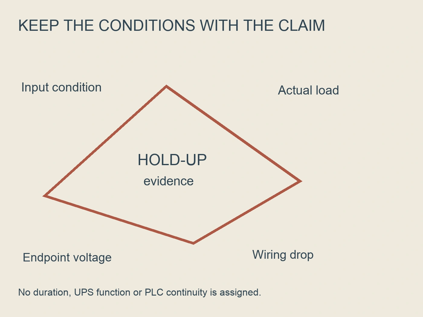
Hold-up information should identify the model, input condition, output load and applicable voltage criterion. It may distinguish typical and minimum values. A figure without those qualifiers can be misleading when copied into a system specification.
PULS's official QT40.241/QT40.242 installation manual illustrates a conditional specification. Its technical-data table lists hold-up time with stated input conditions, while the preceding conditions identify output load and ambient circumstances. That is evidence for those identified PULS devices, not a hold-up rating for RTX-DPS. PULS, QT40.241/QT40.242 installation manual.
For the selected supply, ask what output-voltage boundary defines its published time and whether the listed value is guaranteed under the required condition. If a curve or table covers several loads or inputs, select the condition relevant to the design rather than the most favorable figure.
Do not treat an unqualified typical value as a complete worst-case promise. The required margin and acceptance basis should be established by the responsible system designer using applicable device documentation. This guide assigns no universal margin or interruption duration.
Match the PLC's requirement rather than assume a threshold
The PLC's own documentation should define the permitted supply range and relevant response to undervoltage or interruption. Record the exact CPU or power-input module reference, not merely the controller brand. Remote I/O and other communication devices may need separate review.
A supply's published hold-up endpoint may differ from the PLC's minimum permitted input voltage. Compare those boundaries explicitly. A time measured to one output criterion cannot be used without explanation as the time available above a different device threshold.
The same issue applies to monitoring outputs. A DC-OK indication describes the supply's own monitoring function and threshold. It is not automatically proof that every downstream load is still within specification. The critical load's terminals and operating requirements define the system question.
If the process depends on multiple devices continuing together, identify their requirements in one review sheet. A PLC may remain powered while another essential component changes state. The intended function determines whether that outcome is acceptable; it should not be hidden by reporting CPU continuity alone.
Include actual load and wiring conditions
The power budget should describe the state during the interruption, not only a sum of nominal labels. Identify relevant operating states and any expected transition that changes demand. The exact supply documentation determines which hold-up information applies to those conditions.
Keep DC wiring in the comparison. Voltage at the supply output and voltage at a remote load can differ. The installation review should use the actual circuit lengths, conductor arrangement and load conditions rather than assuming the supply's terminal value appears unchanged everywhere.
Do not assume that a reduced average load establishes the required behavior during every event. The system may have a different demand during starting, an actuator change or a recovery sequence. Record the condition used for the evaluation and any condition not yet covered.
Measurements and interruption verification require an approved qualified method. This article does not recommend switching an operating machine's mains off or introducing an improvised fault. The acceptance plan must define the safe equipment state, instrument method and responsible personnel before any verification is carried out.
What the RTX-DPS family page establishes
Acest RITOKS RTX-DPS 24V DIN-rail power supply page identifies its published reference and output, input and dimensional data. It asks designers to consider the control-circuit load, startup demand and installation temperature, with operating-condition derating to be confirmed.
The public page does not provide an exact hold-up time, an output-decay curve or a model-specific PLC ride-through guarantee. It also does not establish a UPS or buffer function. Those items should remain separate requests rather than be inferred from the supply's rated output power.
For an enquiry, provide the critical-load schedule, actual supply conditions and required interruption objective. Ask for the exact RTX-DPS model's applicable hold-up data and the conditions behind them. If buffering is being considered, request the relevant compatibility documentation rather than assuming a related product can be added without review.
A candidate supply can be commercially suitable for further evaluation while its ride-through requirement remains open. State that distinction in the equipment specification. It prevents a quotation from being mistaken for a completed system-performance review.
Distinguish hold-up from a buffering solution
Ordinary supply hold-up and a dedicated backup arrangement are different selection questions. Hold-up data describe a particular supply behavior under stated conditions. A buffer or UPS arrangement introduces its own capacity, load, connection and operating requirements.
If the required interruption exceeds the documented supply capability, first confirm the actual requirement and evidence gap. A responsible designer can then evaluate an appropriate buffering architecture. Do not treat adding storage as a generic fix without reviewing its interface and the devices it must support.
Also define the recovery objective. Maintaining voltage briefly, completing an orderly shutdown and continuing operation through a longer interruption are different outcomes. A short hold-up figure does not establish all of them.
Avoid promising a time from nominal stored energy alone. Applicable component instructions, operating conditions and system behavior must support the selected arrangement. The project's acceptance plan should describe the demonstrated function rather than a broad claim of “uninterruptible” operation.
Use a conditional compatibility example
Consider a fictional machine with a PLC and remote I/O supplied from one 24V circuit. The customer's requirement is to keep a control function operating through a defined brief AC interruption. The available file contains a typical hold-up figure for a different power supply and a rated-power label for the selected RTX-DPS reference.
The current evidence does not close the requirement. The reviewer needs the selected supply's conditional data, each critical device's permitted input requirement and the relevant wiring/load review. A figure for another supply should not be substituted just because both outputs are nominally 24V.
If the verified conditions support the objective, an approved acceptance plan can establish how conformity is checked. If they do not, the design may need a different documented supply or a reviewed buffering arrangement. If the data remain unavailable, ride-through remains unverified rather than becoming a customer promise.
This is a documentation example, not an account of a RITOKS installation. It provides no RTX-DPS hold-up value or PLC undervoltage threshold.
Record the ride-through decision clearly
| Articol de recenzie | Required record | Decision it supports |
|---|---|---|
| Required function | Critical devices and continuity objective | What must remain operational |
| Disturbance definition | Event duration and relevant waveform | Which input condition is evaluated |
| Supply evidence | Exact model, hold-up criterion and conditions | Available documented output support |
| Load evidence | Actual applicable operating state | Whether the specification condition matches |
| Device requirements | Exact PLC and critical-load limits | Permitted voltage at the loads |
| Installation review | Wiring and voltage-drop basis | Supply data mapped to device terminals |
| Verification plan | Approved criteria and qualified method | What acceptance will demonstrate |
| Open limitation | Missing condition or insufficient evidence | What is not yet promised |
Keep the approved basis with the machine documentation. Replacing a supply, adding a load or extending a DC circuit can change the evaluated conditions. The record should show when the continuity claim needs review rather than imply permanent compatibility for any later modification.
Întrebări frecvente
Does a 24V label imply PLC ride-through?
No. Nominal output voltage does not define hold-up capability or the PLC's response during interruption. Compare exact conditional supply data with the device requirements.
Can a typical hold-up value be treated as guaranteed?
Not without the applicable documentation and design basis. Retain the value's conditions and distinguish typical from minimum or guaranteed information.
Does DC-OK prove every load remains operational?
No. The indication concerns its documented monitoring function. Critical devices have their own supply requirements, and wiring can affect voltage at their terminals.
Is RTX-DPS described as a UPS?
The public page does not establish that function. Request exact hold-up or buffering evidence before making a system-continuity claim.
Referințe
- PULS. (2024, May 7). QT40.241/QT40.242 installation manual. PU-374.015.00-xxF (2024-05-07-AY1), conditional technical-data and hold-up specification. Retrieved October 3, 2026. https://products.pulspower.com/sg/mwdownloads/download/link/id/1671/
- RITOKS. (n.d.). RTX-DPS 24V DIN-rail power supplies. Published selection scope, checked October 3, 2026. https://ritoks.com/products/rtx-dps-24v-din-rail-power-supplies/