
Enclosure Heaters for Control Cabinets · Technical Explainer
Where to Mount an Enclosure Heater and Thermostat
Choosing an enclosure heater is only part of a reliable thermal-management design. Its installed position affects air circulation, cable routing, service access and the temperature that a nearby thermostat senses. A supplier photo may show a compact unit clipped to a rail, but that picture cannot establish where it should sit in every cabinet. The useful buyer question is not simply “bottom or top?” It is: where can this exact heater operate with its required orientation and clearances while its controller measures a representative cabinet condition?
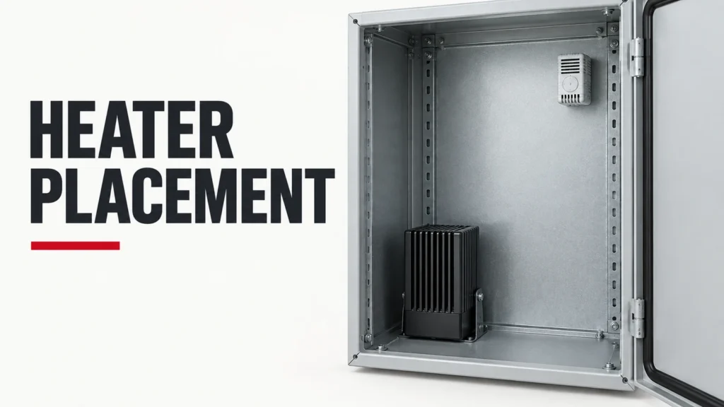
The answer begins with the selected heater's installation manual, the enclosure layout and the objective of heating. For many anti-condensation applications, the design aims to reduce cold surfaces and avoid unfavorable moisture conditions, not to make the entire cabinet hot. Rittal describes enclosure heaters as a means of regulating relative humidity and preventing temperatures below the dew point in its own product information. That is a manufacturer's application statement for its heater family. It does not prove a particular outcome for a different enclosure, load or RITOKS model. The panel builder must evaluate the real cabinet.
Define the space that needs conditioning
Mark the enclosure dimensions, components, cable ducts, door equipment, ventilation paths and likely cold surfaces on a layout. Record whether the cabinet is indoors or outdoors, the ambient range, heat generated by installed equipment and periods when that equipment is off. A machine cabinet that dissipates considerable heat during operation can still cool when idle. Conversely, a continuously loaded cabinet may not require the same heater strategy as an intermittently used enclosure. These conditions tell the designer what the heater must accomplish and where its heat can move.
Acest RITOKS enclosure-heaters category lists the current commercial family and asks buyers to confirm heating technology, capacity, supply, mounting and control requirements. The JRQ series page is the route to its published exact-model information. An available capacity range on a category or family page is not an approved capacity for a project. Selection still requires an enclosure heat-loss assessment and model-specific data, especially if the project has a minimum internal-temperature requirement.
Heater position: seek a clear path for heat, not a slogan
A low mounting point is often considered because warm air rises, but that statement is too broad to be a final installation rule. The heater design may require a specified orientation, spacing from adjacent objects and a particular air path. A small resistance heater without a fan, a fan heater and a PTC element can move heat differently. Manufacturer instructions may permit rail or screw mounting but restrict how the body is rotated. Rittal's heater instructions describe allowable mounting arrangements and explicitly warn against cables contacting the heater body or hot-air outlet. Those warnings show why the exact installation document outranks an internet rule of thumb.
Do not block the heater's inlet or outlet with a wire duct, component, mounting plate or dense cable bundle. Consider service access: an installer must be able to secure the unit and connect it without placing a conductor on a hot surface. Consider nearby heat-sensitive devices and the fire-related restrictions in the manufacturer's manual. The specific clearance value is not supplied here because it varies by model. Request the dimensional drawing and installation instructions before freezing the cabinet layout.
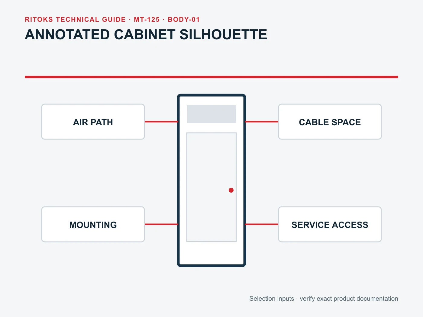
If the enclosure includes a fan heater, the fan's airflow direction matters. If it includes a passive heater, natural convection and free space around the element matter. If the enclosure has shelves or segregation barriers, the heat may not reach the area the designer cares about. Evaluate the actual cabinet geometry instead of extrapolating from a simple empty-box diagram. A local warm pocket next to the heater can coexist with a colder area near the door or a lower compartment.
Thermostat position: measure the condition to be controlled
The thermostat should not be mounted merely where spare DIN-rail space happens to be available. Its sensed temperature must represent the control point. A sensor mounted directly above a heater outlet may switch the heater off based on a local plume rather than the wider cabinet. One mounted beside an air inlet may react to ambient intake air rather than the component zone. One attached to a particularly warm equipment surface may experience a different condition from the air in the enclosure. These are placement risks, not universal prohibitions; the selected controller's instructions and the thermal design determine the best location.
Document the sensor's intended control zone and the allowed mounting method. Some devices sense air at the thermostat body; others can use a remote probe. Do not infer the sensor location from a product title. If a remote sensor is used, check its cable route, connection method and environmental rating. If a controller senses both temperature and humidity, define which variable triggers heating and where the humidity reading is meaningful. Different measured variables cannot be substituted casually.
Setpoint and switching differential also affect the result. A thermostat near the heater may show a rapid temperature rise and cycle before the enclosure's coldest area improves. A remote position may produce a longer heating interval. Neither observation proves the heater is oversized or undersized on its own. The panel builder should evaluate the actual cabinet condition, component limits and manufacturer's controller data rather than use cycling behavior as a guess.
Separate the heater, thermostat and wiring decisions
Heater rating, controller contact rating and circuit protection are independent questions. A thermostat may directly switch a small heater, or it may command a relay; the exact contact data and load characteristics decide. The thermal-layout drawing should show where the heater mounts and the electrical schematic should show which device supplies and switches it. Neither document can replace the other. An apparently sensible physical location can still leave no safe route for the supply cable or a controller with an unsuitable contact rating.
For a cabinet that also includes ventilation, the design must distinguish the heat path from the cooling path. The RITOKS cabinet-cooling-fans category covers a different family, and the cabinet cooling fan selection guide emphasizes model-specific airflow and fit data. A fan can introduce external air, filters, openings and maintenance requirements. An enclosure heater is not a substitute for cooling and a fan is not an anti-condensation heater. If both are specified, document separate setpoints and the intended interaction.
Installation constraints to capture before an RFQ
| Layout field | Why it changes the placement discussion |
|---|---|
| Enclosure dimensions and internal partitions | Shows the available mounting space and possible stagnant zones |
| Rail or plate position | Determines whether the exact heater's approved mounting method fits |
| Heater type and air outlet | Identifies orientation and airflow or convection needs |
| Adjacent cable ducts and components | Reveals blocked heat paths and contact/clearance risks |
| Door, vent and fan positions | Changes where external air or cold surfaces may influence sensing |
| Controller sensor type | Determines whether the thermostat body or remote probe is the sensing location |
| Supply route and service access | Enables safe installation and later replacement |
This table is a request for evidence, not a universal layout specification. It invites the supplier to provide the exact mounting diagram and the panel designer to confirm the location. A photograph of a heater on DIN rail may be useful for identifying its form, but cannot validate clearances, component temperature or condensation performance in a new cabinet.
A practical layout-review sequence
- Define the objective: minimum air temperature, condensation-risk mitigation, frost avoidance or another documented condition. Do not let a heater's published wattage become the objective by default.
- Assemble cabinet inputs: enclosure size, ambient range, installed equipment, duty cycle, openings, likely cold surfaces and existing heat sources.
- Screen the exact heater family for supply, heating capacity, mounting and any integrated control claims. Record which data is published and which requires a supplier drawing.
- Place the heater provisionally where approved orientation, clearance, air path and wiring are all possible. Then identify any compartments or surfaces the heat may fail to reach.
- Place the thermostat or probe where it can measure the condition that should govern the heater. Check that heater plume, fan intake or neighboring equipment does not dominate its reading.
- Review the wiring and contact-rating evidence. A physical placement decision does not establish electrical compatibility.
- Ask the panel engineer to validate the resulting layout and, where appropriate, verify actual cabinet behavior under representative ambient and operating conditions.
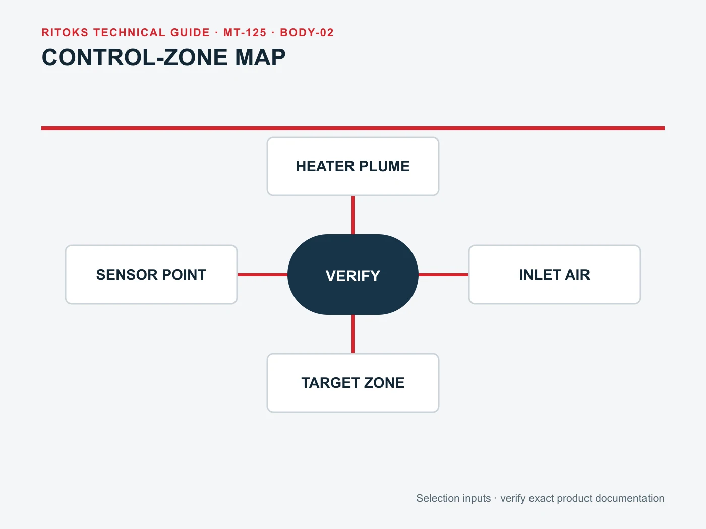
The sequence keeps selection and verification distinct. A supplier can provide model-specific information, but the installer and responsible designer must approve the arrangement in the completed enclosure. For outdoor cabinets, exposure, condensation, ingress and environmental cycling add further questions that cannot be resolved from an indoor illustration.
What the buyer should request
Send a marked cabinet drawing if one exists, the target environmental conditions, the available electrical supply and the reason for heating. Ask for the selected heater's installation instructions, dimensions, approved mounting orientations, clearances, thermal-output details and any control recommendations. Ask separately for the thermostat's sensor location, contact-state diagram, switching differential, electrical rating and mounting requirements. If the heater has a fan, ask for the airflow direction and any obstruction limits. Record any answer that remains project-specific as an engineering check rather than a sales claim.
The final rule is deliberately simple: place neither a heater nor its thermostat by visual symmetry alone. The heater needs a safe, effective path for heat; the controller needs a representative reading; and both require exact-model documentation. The RITOKS thermal-management range provides starting points for product-family screening, while the cabinet layout and manufacturer's manuals govern the final position.