
DC Current Transducers for Industrial Monitoring · Technical Explainer
Unidirectional DC Transducers in Circuits That Can Reverse Current

Quick answer
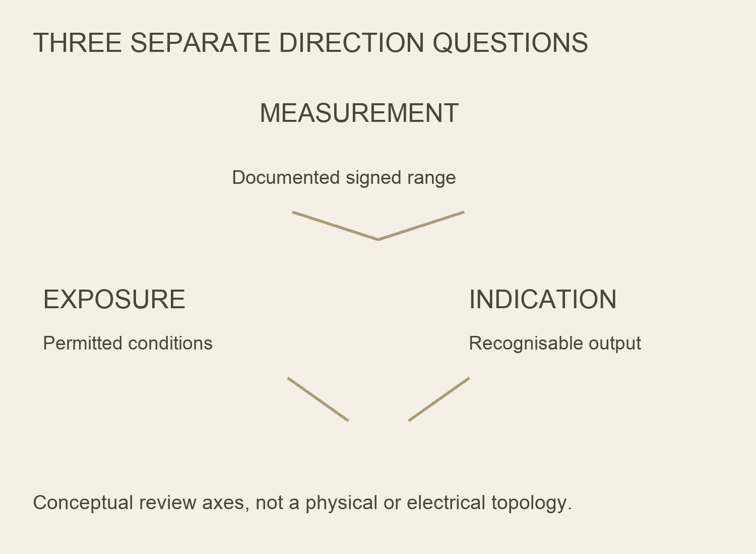
Do not select a unidirectional DC transducer solely because the circuit normally carries positive current. Identify whether current can reverse at the actual measurement location, whether that reverse current must be measured, and what electrical exposure the device must tolerate. Accurate measurement, permitted exposure and recognisable output indication require separate evidence.
A zero-to-positive measuring specification does not establish negative-current accuracy, safe reverse withstand, a particular saturation output or a fault alarm. Request the exact model's signed transfer map, reverse-input limits and out-of-range behaviour. If the application needs both directions, use a documented bidirectional measurement arrangement rather than assuming software can recover information that was never encoded.
This guide defines a procurement decision. It does not authorise reversing connections or forcing negative current through an installed device.
Define positive direction at the actual location
Mark the measurement boundary and positive-current direction on the project drawing. Use identifiable equipment terminals or a documented sensor orientation reference, not an unexplained arrow beside the word battery.
Charging, discharging, regeneration and recirculation can have different meanings at different circuit locations. A current direction identified on one branch is not automatically the direction seen at another measurement point. Establish the actual path with the responsible designer.
Describe the operating states that matter to the channel. Separate normal bidirectional operation from possible reverse exposure during a fault or exceptional event. Those cases may require different measurement and withstand evidence.
The direction definition must reach the controller's channel schedule. If the equipment drawing treats charging as positive and the software treats it as negative, a valid signed output can be misinterpreted without any fault in the sensor.
Separate three requirements that are often conflated
First, define the current range that must be measured with the agreed performance. This may be positive-only or signed, depending on the task. Second, define the relevant electrical and thermal exposures the device must withstand. Third, define what indication the system needs when a current lies outside its accurate measuring range.
These requirements are related but not identical. A device may lack a documented reverse measuring range while its reverse withstand remains unspecified. That absence does not prove either instant damage or safe survival.
Likewise, a measuring range is not automatically a fault-current protection rating. An output representing normal reverse current does not establish safe exposure to every reverse fault. Obtain magnitude, duration and operating-condition evidence for the selected model where the application requires it.
| Requirement | Question to resolve | Evidence that does not answer it alone |
|---|---|---|
| Accurate measurement | Which positive and negative currents are represented within specification? | A technology name or ordinary forward range |
| Permitted exposure | What reverse or overload conditions are allowed? | A signed measuring range without exposure conditions |
| System indication | What output represents an out-of-range or fault condition? | Assumed clipping, zero signal or controller alarm |
| Recovery | What happens after the specified event ends? | A normal-range accuracy figure |
| Receiver interpretation | Can the receiving channel preserve the signed information? | A matching connector or nominal signal label |
This original distinction table is not a completed device assessment. Missing entries should remain supplier questions, not guessed product properties.
Read the selected input specification literally
Acest RITOKS WBI334U01-S DC transducer family presents selected zero-to-positive nominal DC input configurations. Its selected current-output modes do not independently establish signed-current measurement. Acceptance checks for the installed transducer are described in testing zero, span and response.
Do not extend a published positive linear range below zero by symmetry. A zero-to-positive range and a positive overrange statement are not a negative-current specification. Ask for explicit reverse-input information rather than constructing a negative limit from the positive figure.
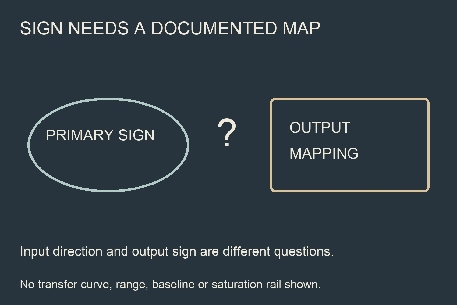
The same caution applies to the output. A current signal can encode many quantities through its mapping, but the particular mapping must be documented. A 4–20 mA label alone does not tell the buyer where zero primary current sits or whether any part of the signal represents reverse current.
If the intended circuit can reverse during normal operation, identify whether the channel is allowed to omit that part of the information. Do not leave the omission hidden behind a generic DC measurement description.
Do not assume every Hall sensor is bidirectional
Hall sensing describes a measurement technology, not a complete signed-range specification. The selected model and output variant still determine how primary current is represented.
Allegro's ACS730 product page explicitly lists bidirectional and unidirectional current-sensing output options in the same family. This is a manufacturer-specific example demonstrating why the technology name alone does not decide direction capability. Its ranges, isolation and response properties are not transferred to RITOKS products. Allegro MicroSystems, ACS730 output options.
Acest RITOKS HS2V H02 open-loop Hall family separately publishes signed measuring ranges for its exact models and a signed voltage-output arrangement. Obtain the selected model's range and mapping; do not collapse all models into one assumed multiple of nominal current.
This makes it a different measurement/interface enquiry from the WBI334U01-S current-output family. It does not make the two products direct PLC replacements or establish unlimited reverse withstand for either one.
Separate primary-current sign from output-voltage sign
Bidirectional measurement does not universally require an externally negative output voltage. Some designs use a biased positive output to represent both negative and positive primary current. Others use a signed output arrangement. The actual transfer map determines the meaning.
TI's CIRCUIT060007 design overview gives a specific single-supply example that maps positive and negative input current into a positive voltage-output interval. Only that distinction is used here; its reference level, ranges, gain and low-side circuit are not instructions for a RITOKS transducer. Texas Instruments, bidirectional current-sensing example.
Record the zero-primary baseline and the direction of output change for the ordered model. Preserve that relationship in the receiving channel's engineering-unit conversion. Do not assume a midscale reference or a signed voltage merely because it is familiar from another sensor.
Where the receiver cannot accept the documented signal, resolve the interface architecture with the designer. Do not clip the signal in software and then claim the full signed current remains available.
Request out-of-range behaviour explicitly
Ask what the output does when the primary current leaves the supported measuring range. The answer needs the exact device, supply/load conditions and specified event scope. Do not invent a saturation rail, a reverse-current alarm or a recovery duration.
LEM's technical FAQs explain measurement limitations and output saturation in the context of different sensor architectures and operating conditions. Those examples support requesting model-specific evidence. They do not define the negative-current behaviour of WBI334U01-S or the fault exposure of HS2V H02. LEM, transducer measuring-range FAQs.
A controller threshold is reliable only when the corresponding output behaviour is documented for the event it is meant to detect. If reverse current could produce an ambiguous or unsupported signal, a normal-looking display is not evidence that no reverse current exists.
Do not use the transducer as a protection function solely because a monitoring output changes with current. A protective purpose requires its own appropriate design and evidence beyond this direction-selection task.
Build a direction-specific procurement register
Gather the following information before comparing products. The register is original and intentionally contains no illustrative current values or test results.
| Register item | Date de intrare ale proiectului | Supplier confirmation |
|---|---|---|
| Measurement boundary | Actual circuit location and positive arrow | Selected orientation/terminal reference |
| Normal operation | States requiring forward or reverse measurement | Signed measuring envelope and transfer map |
| Exceptional exposure | Relevant reverse/overload event assessment | Permitted magnitude, duration and conditions where specified |
| Signal baseline | Meaning of zero primary current | Documented output value and scaling relationship |
| Receiver | Input range, interpretation and channel identity | Compatible signal/interface requirements |
| Out-of-range state | Required diagnostic or reporting purpose | Actual output behaviour and limitations |
| Recovery | What the application needs after the event | Documented recovery behaviour, or an unresolved item |
| Release record | Drawing, order code and evidence revisions | Exact configuration covered by the supplier response |
Give unresolved measurement, withstand and indication items separate owners. This makes it possible to decide whether a missing item affects routine measurement, fault exposure or the monitoring interpretation rather than hiding everything under a broad suitability question.
Decide whether a unidirectional channel meets the task
A unidirectional channel may be considered only within an explicitly supported application. If reverse current need not be measured, the designer must still determine whether relevant reverse exposure is permitted and whether an incomplete indication is acceptable for the defined purpose.
If both directions are required, choose a documented signed-range and compatible receiving arrangement. Do not assume that taking an absolute value, shifting a PLC scale or adding a software sign reconstructs a primary direction the instrument did not represent.
Software can interpret an encoded relationship; it cannot create missing measurement information. Also retain sign where the application needs it. Converting a valid signed signal into a magnitude-only display deliberately removes direction information.
Document any limitation in the channel description and operating instructions. A forward-only monitor should not be labelled complete charge/discharge measurement without the necessary signed evidence.
Keep verification within the approved scope
Request the supplier-approved verification method for the exact configuration and intended direction scope. Qualified personnel should plan the appropriate safe setup. This article does not provide a polarity-reversal procedure, overload test or instruction to disturb a live current path.
Preserve actual observations and their input/output interpretation when a permitted assessment is performed. Keep normal signed-range checks separate from reverse-withstand or recovery tests. Do not use a successful observation at one point to approve an undocumented exposure envelope.
The release package should contain the drawing, transfer mapping, receiver configuration, direction requirements and resolved supplier evidence. If the measurement location or operating states change, revisit the direction assessment rather than simply copying the earlier channel scale.
Întrebări frecvente
Will a unidirectional transducer be damaged by any reverse current?
That cannot be concluded from the measuring range alone. Obtain the exact reverse-exposure limits and conditions. Lack of negative measuring accuracy is not proof of either damage or safe withstand.
Does a 4–20 mA output always represent only positive primary current?
The output label alone does not determine the primary mapping. Obtain the selected model's transfer map. Do not assume signed operation where the product only documents a zero-to-positive input.
Are all Hall current sensors bidirectional?
No. Direction capability depends on the exact model and output variant. Require a documented signed measuring range rather than selecting from technology terminology.
Can PLC software restore reverse current if the sensor does not encode it?
No. Software cannot reconstruct missing direction information. It can interpret a documented signed mapping, provided the receiver preserves that signal.
Referințe
- Allegro MicroSystems. (n.d.). ACS730 current-sensor output options. Exact-family variant example only. Accessed October 2, 2026.
- Texas Instruments. (n.d.). CIRCUIT060007: low-side bidirectional current-sensing circuit. Biased-output design overview only; numerical circuit details not transferred. Accessed October 2, 2026.
- LEM. (n.d.). FAQs about sensors and transducers. Architecture-specific range and saturation discussion, not RITOKS reverse-input limits. Accessed October 2, 2026.