
Skydd mot likström · Jämförelse
Battery Protection Box vs PV Combiner Box: Check the Source Assumptions
Quick answer
A battery protection box and a PV combiner box are not interchangeable because both contain DC components. Compare the actual source arrangement, fault contribution, operating direction, internal topology and exact protective-device duties. An enclosure voltage label or matching port count cannot establish suitability for a different source. Require an assembly-specific review before accepting substitution.
The useful procurement record explains what changed between the original application and the proposed one, and what evidence closes each affected requirement. This guide develops that comparison. It is not an installation procedure, a fault-current calculation or permission to repurpose a stocked enclosure. Circuit design and acceptance belong to qualified personnel using the actual equipment documents.
Compare the intended sources before comparing the boxes
Start with the system one-line diagram and identify the equipment connected to each port. A PV string arrangement and a battery-fed circuit can impose different source and operating conditions. The reviewer needs the actual project inputs rather than a generic assumption that every DC source behaves alike.
Eaton's solar circuit protection guide describes PV source protection in the context of limited available fault current and equipment intended to operate under those conditions. Its network illustration separates PV source circuits, output circuits and inverter interfaces. That manufacturer example explains why the source and circuit location matter; it does not provide a fault study or a protection selection for an arbitrary battery system. Eaton solar circuit protection application guide
Obtain battery fault-source information from the applicable battery and system documents. Record the relevant condition and the sources that can contribute under the approved topology. Do not substitute a PV module short-circuit figure or a box's normal operating-current label for that information. The task is to establish the input to the protection review, not to manufacture a convenient comparison value.
Also avoid a universal ban on every cross-application component. Eaton's current photovoltaic-fuse family page includes battery-storage applications in its broad scope. That is not approval of any individual fuse or assembled PV box for every battery circuit. It demonstrates why exact component evidence is more useful than assuming that an application word always allows or always prohibits a substitution. Eaton photovoltaic-fuse family
Keep the actual RITOKS configurations distinct
Den TPBAT4-B7 battery protection box page presents a pictured four-input, four-output battery-distribution configuration. It asks for the battery bus information, one-line diagram and exact protection bill of materials. The representative photograph does not establish every custom assembly's voltage, internal node map or fault capability.
Den LQX-N PV combiner family documents model-dependent input/output arrangements with QS, surge protection and fuses. Its page asks buyers to confirm the exact component ratings and project wiring. That information supports a PV-family enquiry; it does not establish compatibility with the TPBAT battery application.
Compare exact configurations rather than family titles. The same input count can accompany different output counts and internal relationships. Request the drawing for the selected variant and identify which ports share nodes. A proposed substitution should explain whether it changes source relationships, protective paths or operating functions, not simply show that the enclosure fits the available space.
Keep missing information visible. If the product page does not identify a specific fuse, breaker or switch order code, the comparison record should say that the bill of materials is required. A familiar component silhouette does not supply its duty, installation conditions or approval for the proposed circuit.
Build a source-assumption comparison sheet
Use the following worksheet to record original and proposed application inputs. It supplies evidence questions rather than universal acceptable values. The designer should determine which conditions govern the actual assembly and what source documentation is needed for each one.
| Jämförelsefält | Information for the original application | Information for the proposed application |
|---|---|---|
| Source identity | Exact PV strings, batteries or other connected sources | Exact sources replacing or adding to them |
| System operating conditions | Documented voltage and intended current duties | Corresponding conditions for the new system |
| Fault contribution | Relevant source study and circuit location | Updated study covering all contributing sources |
| Energy direction | Approved operating states and source/load relationships | States introduced or changed by the substitution |
| Internal topology | Exact port-to-node and protective-path drawing | Drawing that preserves or revises required relationships |
| Equipment interfaces | Relevant inverter or converter requirements | Requirements of the connected replacement equipment |
| Evidence scope | Conditions covered by existing records | Conditions not yet demonstrated for the new application |
The comparison should identify document revisions and owners. If a source contribution is unknown, assign the missing information to the responsible supplier or designer. Do not enter the box's rated current in that field just to produce a complete table. A normal-current requirement and a fault-source assessment serve different purposes.
Avoid relying on a single favourable field. A voltage comparison can identify one requirement without settling current duty, protection performance or topology. Likewise, a shared enclosure format does not prove the internal component arrangement remains appropriate after the source changes.
Review direction and topology as separate requirements
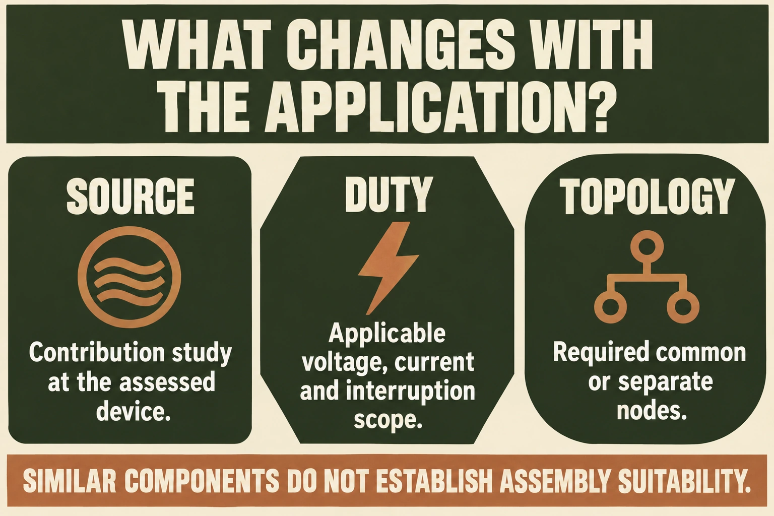
A battery-related circuit may need review of both charging and discharging states where those states are actually supported. A PV arrangement also needs its documented source and downstream relationships considered. Do not reduce either system to an unqualified arrow on a product photograph.
Record what equipment can energize each connection in the approved system, including alternate operating states. Ask the protective-device supplier about any direction or polarity conditions applying to the exact selected component. A generic DC label does not document its suitability for every possible source direction or terminal arrangement.
Topology is another question. A combiner's intended shared connection does not automatically match a project needing distinct battery branches. Conversely, a multi-port battery enclosure does not necessarily combine its inputs. Obtain the actual node map and compare it with the system requirement before accepting either label as a circuit description.
Keep source compatibility outside assumptions about enclosure capability. If the proposed common node connects battery banks, obtain the applicable bank-connection review. A supplier's confirmation that a terminal carries the requested current does not authorize the sources to be joined. The assembly review and source review should cite each other without becoming the same decision.
Match protective functions to the exact component list
For every protective function, request the exact component reference and its applicable documentation. Separate overload or short-circuit protection from isolation and surge protection. The presence of several protective-looking modules does not show that all required duties are provided, coordinated or valid under the changed source conditions.
The LQX-N family lists a QS, SPD and fuse arrangement, while TPBAT requires confirmation of the internal breaker or fuse bill of materials. These descriptions should remain attached to their published configuration scope. Do not claim that every battery box contains fuses, or that every PV box has the same components as the pictured battery assembly.
| Assembly-review task | Bevis som ska begäras | Conclusion to avoid without it |
|---|---|---|
| Overcurrent protection | Exact device data and application review | A matching ampere label proves adequate fault protection |
| Switching or isolation | Exact device function and permitted operating duty | A carrying-current figure proves load interruption |
| Överspänningsskydd | Selected device identity and circuit suitability | Any SPD suits any DC source arrangement |
| Shared connections | Node drawing and relevant connection requirements | Identical port counts prove equivalent topology |
| Thermal arrangement | Applicable assembly evidence and configuration conditions | A component rating alone establishes whole-box performance |
| Short-circuit assessment | Relevant study and assembly/component evidence | One enclosure voltage label establishes every fault duty |
These are original review questions, not a claim that either published family already has a particular tested assembly rating. Obtain the actual evidence for the quoted order and ask the responsible reviewer to explain its applicability. No universal test method or numerical acceptance limit is supplied here.
Keep assembly evidence separate from component evidence
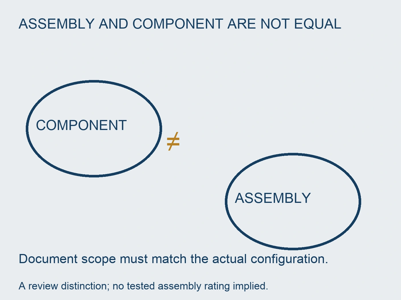
A component document covers the scope it states. An assembly includes the selected components and their actual arrangement, connections and enclosure conditions. The reviewer should identify which evidence concerns an individual device and which evidence concerns the proposed box. A stack of datasheets is not automatically a complete assembly assessment.
Ask which configuration any supplied temperature-rise or short-circuit record represents. If the quoted assembly differs, identify the difference and obtain the relevant review. Do not rewrite the record's model name or extend its conditions to a new application without the issuer's or responsible designer's support.
Keep the delivery inspection plan tied to the agreed drawing and component list. Markings, port identity and configuration checks can support a handover record, but their completion does not replace the underlying source and protection decisions. Expected evidence and actual inspection results should remain distinct.
A substitution record should therefore state the proposed assembly, the changed application inputs, documents reviewed and remaining exclusions. It should be understandable after procurement staff change. “Equivalent DC box” is not an adequate explanation of what was assessed or which conditions remain unsupported.
Change the source duty in a filled comparison
Imagine a fictional PV proposal P1 whose designer assigns two contributing paths of 9 A each through the protective device being assessed for one particular fault case. The defined sum is 9 + 9 = 18 A. It is not a universal PV fault formula or a specification for an LQX-N input. Other sources, current histories and fault locations would need their own study. Assume the chosen point and current definition are kept consistent in this teaching comparison.
The fictional device document E1 states an upper DC interruption duty of 1000 A under its identified conditions. A current of 18 A being below that upper value does not approve P1. The lower interruption scope, operating time, voltage, circuit conditions and protected-item limits still matter. This is precisely why a large breaking-capacity headline cannot replace the original PV protection review, even before a different source is proposed.
Now change the request to a fictional battery-fed arrangement B1 whose system study assigns 1200 A through that same assessed device position. Treat this as a supplied teaching input, not a calculated battery fault or TPBAT rating. Keeping E1's applicable conditions unchanged for this comparison, 1200 A exceeds its assumed 1000 A upper duty by 200 A. The original proposal's document cannot establish interruption coverage for that new case. Matching enclosure voltage or normal operating current would not resolve the specific upper-duty mismatch.
Do not use the ratio between 1200 A and 18 A as a universal battery-versus-PV multiplier. These numbers belong to two invented source assessments. A real battery or PV system can have additional source contributions, limiting equipment and time-dependent behavior. Nor should the current at the overall fault be copied into every branch-device row. The responsible study must identify what actually passes through each item, with the quantity definitions and conditions needed for manufacturer comparison.
Suppose revised component evidence closes B1's interruption question. The substitution still needs its topology and operating-direction review. If P1's common collection node joins sources that B1 requires to remain separate, a higher-capability protective device does not restore that boundary. Similarly, a component accepted for both application types does not establish the enclosure's temperature-rise or short-circuit assessment for its revised population. Closing one document mismatch should expose, not conceal, the remaining configuration questions.
The practical alternatives are to retain the original application, propose a documented battery configuration or hold substitution pending named evidence. The filled comparison identifies why the decision changes: source duty, node requirements and component-versus-assembly scope, not the letters DC on the label. It rejects use of E1 for the hypothetical 1200 A case without declaring every PV fuse or combiner universally unsuitable for batteries. No live fault test, actual capacity, approved pairing or enclosure repurposing instruction follows from these numbers.
Conclusion
Compare battery and PV boxes through their actual source assumptions and documented functions. Keep topology, component duty and assembly evidence separate until each requirement has been resolved. An acceptable substitution is a decision about a defined configuration in a defined system, not a general equivalence inferred from DC labels, photographs or the number of ports.
Källor
- Eaton. (2017, October). Solar circuit protection application guide, Publication 10191 / BU-SB14309. PV network and source-protection discussion; legacy guide, not current project code evidence.
- Eaton. (n.d.). Bussmann series photovoltaic fuses. Family application scope does not establish exact-device or whole-assembly suitability.
- RITOKS. (n.d.). TPBAT4-B7 four-way battery protection box.
- RITOKS. (n.d.). LQX-N PV combiner box.