
Electrical Measurement & Monitoring · Technical Explainer
Building a Reliable Channel Map for Branch Current Monitoring
Quick answer
A reliable branch-current channel map connects the physical circuit, sensor, module input, digital data point and platform tag in one revision-controlled record. Keep a stable circuit identity separate from its changeable display name. Confirm the exact sensor pairing, signal interpretation and communication configuration before accepting the mapping.
Sixteen available channels do not prove which circuit each reading belongs to. A plausible current value or matching channel number on two screens is not independent evidence of the complete route. Record authorised verification and update the mapping after physical or software changes, without silently assigning old readings to a new circuit.
This guide prepares a handover register. It provides no live sensor-swapping, CT shorting or wiring procedure, and no fabricated commissioning readings.
Give the circuit a stable identity
Start with an identifier that links the circuit to the panel schedule and current drawing. Keep the breaker reference, load name and physical location as separate fields. A human-friendly name can change without changing the underlying circuit identity.
If a load moves to another circuit, record both the move and the identity decision. Do not assume that reusing a display label makes historical readings comparable. The equipment, feeder and measurement boundary may have changed.
Distinguish panel identity from module identity. Several modules can have an input labelled channel one, so the channel number alone is not a unique source. Include the exact module and its physical input in the map.
Use the register to resolve naming differences between electrical drawings, maintenance records and the platform. Do not allow several informal names to obscure whether they refer to one circuit or different loads.
Identify the paired sensor architecture
Obtain the exact module configuration and supported sensor/input documentation. A description such as external CT does not establish the secondary signal, permitted range, sensor ratio or connection requirements.
Schneider's branch-monitoring documentation FAQ describes a particular system with different sensor constructions and dedicated installation documents. This is a manufacturer-specific example of why the sensor arrangement and its matching documentation matter. Its channel count and capabilities are not transferred to RITOKS. Schneider Electric, branch-monitoring documentation.
For the RITOKS 16-channel AC current-monitoring module, request the order code, selected input architecture, compatible sensor list, input range and exact channel diagram. The public page does not supply a universal sensor pairing table or default scaling values.
Record the actual sensor identity at each input rather than merely writing CT against every row. Where several sensor models are used, the map must preserve those distinctions so a replacement is not selected from appearance alone.
Keep sensor handling tied to its instructions
Sensor architecture affects both interpretation and safe handling. Do not apply one generic action to every component called a CT.
Schneider's current-transformer installation FAQ warns about hazardous conditions from open current-output CT secondaries while primary current flows and identifies the importance of polarity/orientation. This supports requiring qualified personnel and the selected device's instructions, not improvising channel checks in a live panel. Schneider Electric, CT installation information.
A different Schneider FAQ states that the auxiliary CTs of its BCPM example have voltage secondaries and must not be shorted. This contrast shows why a current-output CT handling rule cannot be applied indiscriminately to another architecture. It does not establish the RITOKS sensor type. Schneider Electric, BCPM auxiliary CT clarification.
The channel map should record the approved sensor diagram and relevant orientation reference. It should not become an unofficial shorting, opening or polarity-reversal instruction. Leave physical work and verification to qualified personnel under the exact authorised method.
Build the physical-to-digital chain
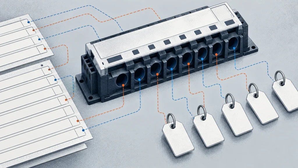
Each map row should follow one reading from its physical source to its final meaning. Record the circuit, sensor, module channel, communication identity, data-point interpretation and platform tag. Keep document revisions beside the values that depend on them.
Do not assume that an input numbered one maps to a register or platform point numbered one. The manufacturer's map may use another convention, and an integrator may have renamed the platform point. Resolve the chain from actual documents and configuration.
Use this original register structure for the handover. It contains required evidence fields, not invented addresses or sensor ratios.
| Map layer | Record to preserve | Evidence linking it to the next layer |
|---|---|---|
| Physical circuit | Stable circuit ID, panel, breaker and load boundary | Current drawing and circuit schedule |
| Sensor | Exact identity, architecture and applicable orientation reference | Approved sensor/module pairing and diagram |
| Module input | Module identity and physical channel | Exact terminal/channel document |
| Data point | Selected protocol, device identity, address and format | Configuration-specific register or data map |
| Interpretation | Units and confirmed scaling/range | Manufacturer mapping and receiver configuration |
| Platform tag | Stable source reference and human-readable name | Saved point/tag configuration |
| Verifiering | Actual authorised check record and unresolved items | Evidence linking the full chain, not only a plausible value |
Where a field is unsupported or unknown, retain that status. A complete-looking row assembled from assumed defaults is less useful than an honest map with a supplier question assigned to an owner.

Preserve data format as well as address
A digital address alone is not enough to interpret a reading. Obtain the exact data format, units and applicable scaling information from the selected configuration's map. Keep any documented channel numbering or indexing convention explicit.
If the receiving system requires additional interpretation details, record them rather than copying another device's settings. A data point can be reachable while its displayed value is still incorrectly interpreted.
The RITOKS public page lists Modbus RTU/TCP options. Confirm which option belongs to the ordered unit and obtain its actual documentation. Do not assume every unit simultaneously supports every listed interface or has the same addressing arrangement.
Protocol selection and device identity must also remain distinct from physical channel identity. A communication address change can affect the platform route without moving a sensor. A sensor move can change the physical source without changing the communication address.
Make the platform tag describe the measured quantity
Use a tag name that identifies the intended circuit and quantity. Retain its stable source identity separately so a cosmetic name change does not erase the underlying route.
A branch-current reading should not be labelled branch energy merely because the platform supports energy dashboards. The module's published AC current inputs do not independently establish voltage inputs, power calculation or energy accumulation. The limits of energy estimates from current data are explained in why branch current alone does not prove branch energy.
Likewise, a tag carrying a phase name is not proof that the physical sensor is on that phase. The phase/conductor identity, where relevant, comes from the actual circuit evidence and authorised verification.
Avoid using the display name as the only commissioning record. It describes intended meaning, but the map and verification must establish whether the signal actually represents that meaning.
Validate the map without inventing readings
Agree a verification scope with the supplier and responsible commissioning team. The method should be appropriate to the actual sensor/module architecture and site conditions. This guide does not specify a live load-switching or sensor-swapping sequence.
Document what evidence links each physical source to its digital point and tag. Save actual observations, conditions and reviewer identity when a permitted check is performed. Do not prepopulate the register with illustrative readings that resemble acceptance results.
A believable value on the screen does not prove the source. Two circuits can produce similar currents, an incorrect scale can look plausible and a copied tag can display a different channel's data. The verification needs to address identity as well as numerical interpretation.
When an inconsistency appears, preserve the original configuration and record the correction. Rechecking the affected chain is different from silently changing a tag until the screen looks sensible.
Control changes at every layer
A channel map can become stale after a circuit move, sensor replacement, module replacement, address change or platform edit. Each event affects a different part of the chain, so record the actual change rather than replacing the whole row without explanation.
Keep before-and-after identities, the effective time, reason, authorisation and affected documents. Preserve the actual re-verification evidence for the changed chain. The change record should let maintenance staff determine which mapping was valid when a historical reading was captured.
| Change event | Map fields to review | Historical interpretation question |
|---|---|---|
| Circuit moved | Physical circuit, channel and drawing references | When did the old channel stop representing that circuit? |
| Sensor replaced | Sensor identity, pairing, scaling and diagram | Does the earlier conversion still apply? |
| Module replaced | Module/configuration identity and data map | Are addresses, formats and channels unchanged or revised? |
| Communication identity changed | Protocol/device route and platform configuration | Does the stored source still point to the intended module? |
| Tag renamed | Name and stable source relationship | Was this cosmetic, or did the measured source also change? |
| Receiving scale corrected | Interpretation and correction record | Which earlier results require qualification or review? |
This original change table is a handover aid, not a new software workflow. Use the project's existing document-control process rather than inventing an unnecessary monitoring system.
Keep historical data attached to the correct source
Do not silently rewrite old data labels when a new load takes over a channel. A historical record belongs to the source and interpretation valid at the time, not whichever load currently occupies the input.
If the platform cannot retain the required source history automatically, document the transition boundary through the existing project record. Make the limitation visible to users comparing trends across the change.
A corrected scaling or mapping may require review of previous reported values. Distinguish a documented correction from original observations, and retain the reason and method. Do not claim the platform recovered unmeasured energy or independently proved a saving.
Trend comparisons are meaningful only within the stated measurement and interpretation scope. Channel continuity in the database is not necessarily physical-circuit continuity in the cabinet.

Hand over the evidence package
Provide the current map, approved sensor/module documents, circuit drawing, selected communication map and platform configuration references. Attach actual verification and change records, including unresolved items and their owners.
Procurement needs the exact orderable configuration and pairing information. Commissioning needs the approved physical and digital route. Operations needs stable circuit meaning and the history of changes. One register can connect these responsibilities without pretending that a product catalogue is an as-built record.
Review the affected rows when work changes a circuit or receiving configuration. Keep the map usable at the cabinet and in the platform documentation, with the same revision reference. A maintained identity chain is the result; channel count alone is not.
Vanliga frågor
Does a 16-channel module automatically identify sixteen circuits?
No. It provides inputs within its selected configuration. The physical circuit, sensor, channel, digital point and platform meaning still need to be mapped and verified.
Is a plausible current value enough to accept the mapping?
No. Verify identity and interpretation as well as numerical plausibility under the authorised method. Similar currents or copied tags can conceal a mismatch.
Can every external CT be handled with the same shorting rule?
No. Identify the exact sensor architecture and use its approved instructions. Manufacturer examples include different secondary types with different restrictions.
Can branch-current data be labelled energy use?
Not without the required supported measurement and calculation scope. Current-only inputs do not independently establish power or accumulated energy.
Källor
- Schneider Electric. (2015). Branch circuit monitoring documentation, FA239501. Exact-system sensor/documentation overview; linked attachments not represented as reviewed. Accessed October 2, 2026.
- Schneider Electric. (2007). Square D current-transformer installation information, FA219147. Architecture-specific safety and orientation context, not a universal field procedure. Accessed October 2, 2026.
- Schneider Electric. (2009). BCPM auxiliary CT secondary clarification, FA208380. Exact voltage-secondary example; not RITOKS sensor identification. Accessed October 2, 2026.