
Bridge Rectifier Modules · Technical Explainer
Calculating Bridge Rectifier Loss from the Actual Conduction Path
Identify the bridge before counting conducting devices
Start with the actual internal circuit. The MDQ single-phase bridge rectifier family is described as a four-diode single-phase bridge (RITOKS, n.d.-b). The MDS three-phase bridge rectifier family is a different three-phase architecture (RITOKS, n.d.-a). Their family names establish a purchasing starting point, not identical waveforms or interchangeable current definitions.
For a conventional single-phase full bridge, the normal load-current path includes a pair of diodes in series. Which pair conducts changes with the supply polarity. A conventional three-phase diode bridge also has a path through an upper and lower device during a conduction interval, but its device conduction intervals differ from those of a single-phase bridge. Use the circuit drawing to identify these paths rather than counting terminals in a photograph.
Treat commutation intervals, special internal configurations and additional components according to the actual design. A calculation that assumes two conducting devices must say which conventional bridge and operating approximation it represents. Do not extend that assumption automatically to a center-tapped rectifier, a controlled bridge, a parallel assembly or a bridge with extra semiconductor functions.
Semikron Danfoss's application manual distinguishes per-device forward characteristics and thermal parameters from module-level data in its bridge-rectifier discussion. Its notation makes clear why the engineer must know whether a quoted parameter applies to one diode, one thyristor or the complete module (Semikron Danfoss, n.d., section 7.2.6.2).
Use device current rather than a convenient output label
Output average current is a system quantity. Individual diode average and RMS current depend on the conduction intervals and waveform. Keep these quantities separately named throughout the worksheet so a spreadsheet cell cannot silently change meaning between the electrical and thermal calculations.
For an idealized symmetric bridge with continuous output current, symmetry can help derive per-device currents. However, symmetry is an assumption to document, not permission to ignore unbalanced supplies, discontinuous conduction or a capacitor-input load. If a validated simulation or measurement supplies device waveforms, retain those waveforms and their operating conditions.
Capacitor-input rectifiers can draw current in concentrated charging intervals rather than throughout the cycle. The same output average current therefore does not establish the same diode RMS current as a smoother load. A loss estimate based on average current alone may miss the resistive part of the forward characteristic.
| Antal | Definition in the record | Source to retain |
|---|---|---|
| Output average current | Average DC load current over the stated interval | Load requirement or validated waveform |
| Device average current | Average current through one specified diode | Conduction schedule and device waveform |
| Device RMS current | RMS of that same device current | Integration interval and waveform data |
| Instantaneous forward voltage | Voltage at the instantaneous device current and temperature | Exact forward characteristic or validated model |
| Total bridge conduction loss | Sum of the individual conducting-device losses | Device list and calculation assumptions |
When a datasheet gives a nominal current designation, read its specified thermal and circuit conditions. The MDS family page explicitly leaves exact voltage, mounting and thermal requirements to model-specific documentation. A model name is not the missing waveform or forward characteristic needed to close the loss calculation.
Calculate average conduction loss consistently
The direct definition is the average of instantaneous forward voltage multiplied by instantaneous forward current over a stated observation period. For each diode, evaluate its own voltage-current product during its conduction intervals, then sum the average losses of all devices in the bridge. Include zero-current intervals in the averaging period; otherwise the result becomes conduction-interval average rather than full-period average.
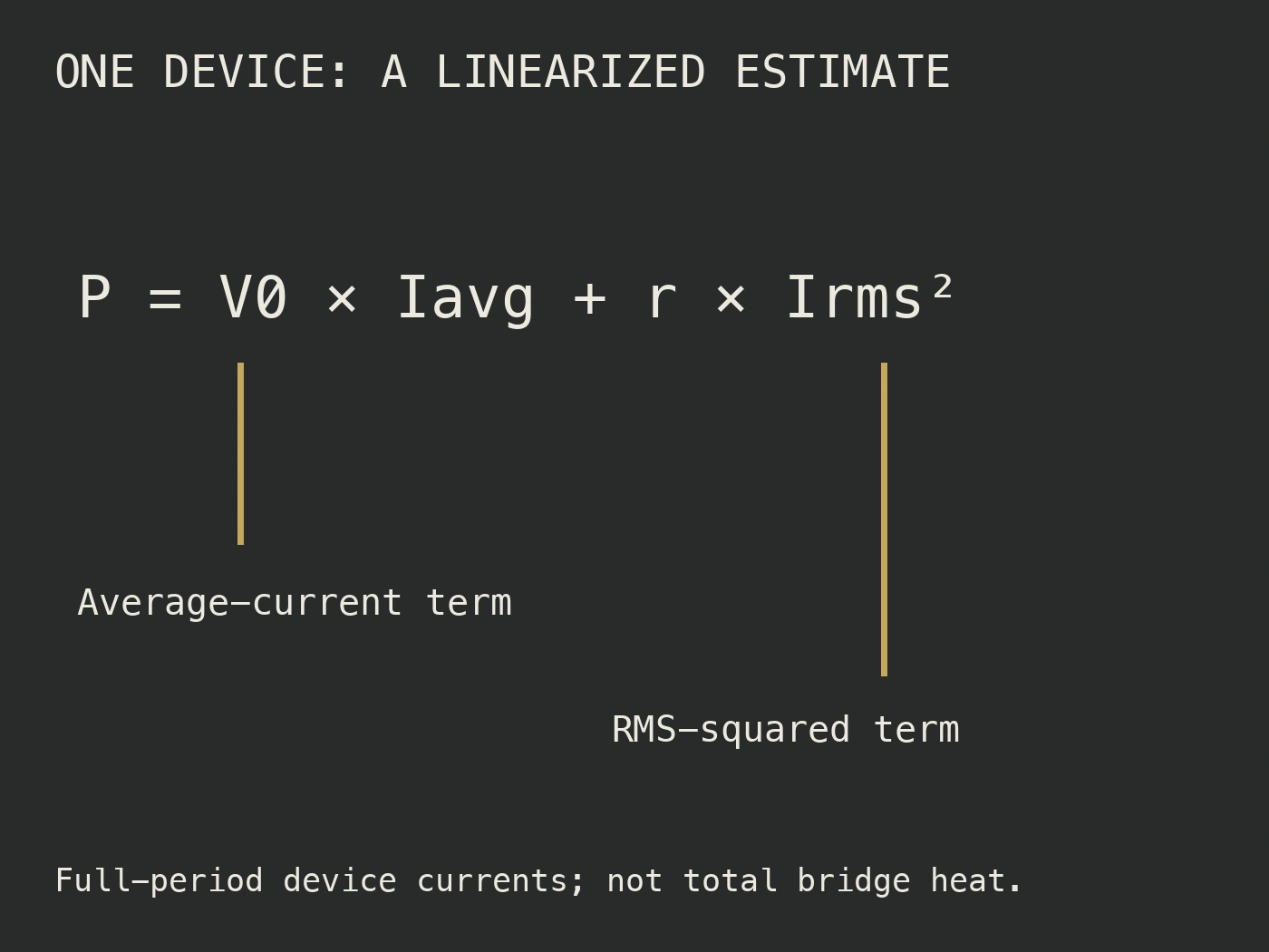
A common linearized forward-characteristic model uses a threshold voltage and a slope resistance at a chosen junction temperature. In that approximation, per-device average conduction loss is:
P_device = V_F0(Tj) × I_device,avg + r_F(Tj) × I_device,rms²
Semikron Danfoss gives this average conduction-loss form for rectifier and AC-controller calculations and describes the formulas as rough estimates useful for cross-checking simulation results (Semikron Danfoss, n.d., section 6.1.1). The threshold and slope must come from the applicable device data or approved fit; neither is a universal silicon constant.
Use the same averaging period for average and RMS current. Preserve amperes, volts and ohms explicitly so the result is watts. Do not insert the square of average current where the formula requires RMS current squared. Those quantities coincide only for a constant waveform over the averaging interval, which is not generally the current through one bridge diode.
If instead the model uses a nonlinear forward-voltage curve, integrate the curve's voltage at each current value against that current. Do not combine a nonlinear voltage estimate with a slope-resistance term already represented by that curve; that would count part of the voltage drop twice. Record which method was used and why its temperature and current range fit the intended duty.
A transparent hypothetical comparison
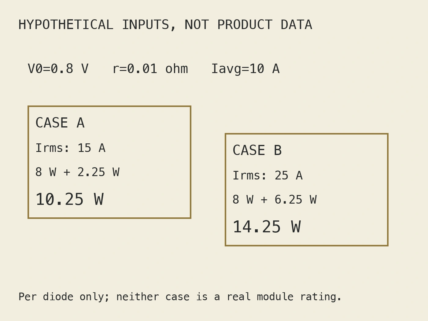
Consider one hypothetical diode calculation using a chosen linearized model with threshold voltage 0.8 V and slope resistance 0.01 ohm. These are invented teaching inputs, not MDQ, MDS or manufacturer specification values. Compare two assumed full-period device waveforms with equal average current but different RMS current.
| Hypothetical device case | Average current | RMS current | Calculated threshold term | Calculated resistive term | Calculated device loss |
|---|---|---|---|---|---|
| Case A | 10 A | 15 A | 8 W | 2.25 W | 10.25 W |
| Case B | 10 A | 25 A | 8 W | 6.25 W | 14.25 W |
The arithmetic demonstrates why equal average current does not imply equal conduction loss. Case A uses 0.8 × 10 + 0.01 × 15²; Case B uses 0.8 × 10 + 0.01 × 25². The difference comes from the assumed RMS currents, not from a claimed difference between two real products.
These are per-device results. Do not label either as total bridge loss without determining the waveforms and losses of the other devices. A symmetric design may justify equal losses among its devices, but that symmetry must be supported by the actual conduction schedule and operating assumptions.
The example also does not prove a heatsink is adequate. It supplies neither thermal resistance nor ambient and cooling conditions. Keep the loss worksheet and thermal-network calculation connected but distinct, so a correct electrical sum cannot accidentally be reported as complete thermal approval.
Link the electrical estimate to temperature
The forward characteristic depends on junction temperature, while the estimated loss contributes to that temperature. State the initial temperature assumption and check whether the resulting thermal calculation is consistent with it. Where an iterative or simulation method is used, retain its convergence conditions and model source rather than publishing only the final wattage.
Use thermal parameters with the scope given in the datasheet. Per-diode junction-to-case data and module case-to-heatsink data describe different parts of the thermal path. Adding or multiplying parameters without checking their definitions can create an apparently precise but physically mismatched result.
For changing load duty, average loss alone may not answer the temperature question. The equipment's transient thermal behavior and duty sequence may matter. Request the applicable thermal data and have the responsible engineer decide whether a steady-state estimate is sufficient or whether a transient calculation is required.
Conduction loss is also not every possible loss in the assembly. State what the worksheet includes and excludes, including switching or recovery effects where relevant, auxiliary semiconductor components and other cabinet heat sources. The manufacturer's rectifier approximation must not become a blanket claim that dynamic losses are always zero.
Assemble a useful thermal-selection request
The commercial request should supply the calculation's inputs, not merely “a bridge for this current.” Identify the exact topology, supply conditions, load waveform, expected duty and cooling arrangement. Ask for the forward-characteristic data and thermal parameters for the proposed order code under their stated conditions.
| Recensionsobjekt | Evidence needed | Keep open when |
|---|---|---|
| Internal conduction path | Exact circuit diagram | Family description does not establish the ordered circuit |
| Device current waveform | Validated simulation or appropriate measurement | Only output average current is available |
| Forward characteristic | Applicable curve or linearized parameters | Temperature or fitting range is unspecified |
| Module loss sum | Identified device list and averaging method | Per-device and total-module values are mixed |
| Cooling assessment | Thermal data and intended installation conditions | Heatsink assumptions have not been checked |
Den bridge rectifier module category can help identify relevant families, but it cannot supply a shared loss curve for every member. Keep the selection tied to the requested model and its documents. Do not substitute a larger current designation for the missing thermal calculation.
Common loss-calculation questions
Can I multiply output current by one diode voltage drop?
Not as a general complete-bridge calculation. You must identify the conducting path and the current through every device. A constant-drop approximation can be a stated preliminary method, but its device count, waveform assumptions and parameter scope must be explicit. It does not replace exact thermal-selection evidence.
Why does RMS current appear in the linearized formula?
The slope-resistance contribution is proportional to instantaneous current squared. Its full-period average therefore uses RMS current squared. The threshold-voltage contribution instead uses average current. Keeping those terms separate makes the effect of pulsed current visible rather than hiding it inside an arbitrary voltage drop.
Does a calculated bridge loss prove the module will run safely?
No. The calculation must be checked against the exact semiconductor and thermal data, cooling arrangement, duty and temperature limits. It is also separate from protection, mounting and electrical compatibility. A numerical worksheet is evidence for one part of the design, not universal approval of the assembly.
Conclusion
Calculate bridge rectifier loss from the actual device conduction paths and waveforms. Keep output, per-device average and per-device RMS current distinct; use temperature-appropriate forward characteristics; and sum losses with clear parameter scope. Preserve assumptions and unresolved inputs so the thermal reviewer can evaluate a real design rather than an unexplained wattage.
Källor
- RITOKS. (n.d.-a). MDS 30A–250A three-phase bridge rectifier module. https://ritoks.com/products/mds-three-phase-bridge-rectifier-30a-250a/
- RITOKS. (n.d.-b). Single-phase bridge rectifier modules. https://ritoks.com/products/single-phase-bridge-rectifier-modules/
- Semikron Danfoss. (n.d.). Application manual power semiconductors (AB509142199100en-000205, sections 6.1.1 and 7.2.6.2). https://assets.danfoss.com/documents/latest/530447/AB509142199100en-000205.pdf