
DC Power Protection · Technical Explainer
Buying PV Cable Assemblies: Define the Pinout and End-to-End Tests
Quick answer
Buy a PV cable assembly against a controlled endpoint drawing, not a photograph. Identify the connector manufacturer and exact part at each end, map every contact to its intended circuit, and define cable construction, length datums and acceptance records. Continuity, insulation and workmanship checks answer different questions; agree their methods and limits before production.
This guide is for buyers reviewing finished leads and branch assemblies. It is not a live-system test procedure. Electrical tests, isolation arrangements and instrument settings belong to qualified personnel working to the applicable connector instructions and an approved test plan. A continuity pass alone does not approve a lead for its intended voltage, environment or mating equipment.
Freeze the endpoint identity before discussing price
An assembly enquiry should distinguish three identities: the finished lead, its individual connectors and the mating equipment. Assign a drawing reference to the lead, list both connector parts, and identify the permitted counterpart on the module or inverter. A generic description such as “solar extension cable” leaves too much room for substitution.
Stäubli's cross-connection statement rejects mating its connectors with other manufacturers' products. That manufacturer position is a reason to ask for exact mating identities, not permission to treat a similar housing as interchangeable. Keep any proposed connector-system change outside the approved bill of materials until the relevant equipment and connector manufacturers' requirements have been reviewed. Stäubli cross-connection guidance
Den RITOKS RTX-PVC connection family separates its panel connector reference from cable-mounted pairs, branches and extension assemblies. That distinction matters when preparing an enquiry: the panel connector's listed values do not establish the ratings of an extension lead. Request the evidence for the exact quoted assembly rather than copying another row from the family page.
Use photographs as supporting identification, with a part label visible where available. They should accompany the drawing, not replace it. If the supplier cannot identify a connector beyond a marketing phrase, record that endpoint as unresolved and avoid releasing production on appearance alone.
Write a pinout that cannot be reversed by interpretation
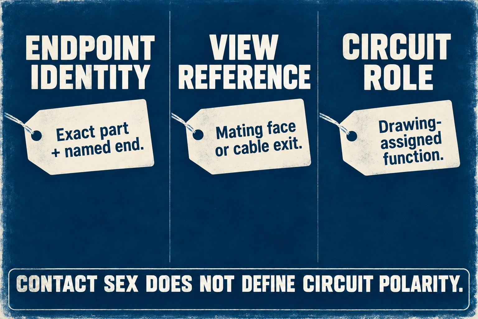
A useful pinout connects a named endpoint and contact to a named circuit. The drawing should say whether the view looks into the mating face or at the cable exit. Shell shape, contact sex and electrical polarity are separate attributes. Do not infer positive or negative solely from the terms male and female, cable color, or an unlabelled close-up.
For a single-conductor extension, the connection schedule may be simple, but endpoint orientation still matters. For a branch lead, show which conductors join and which remain separate. Any branch identifier should appear in the drawing, label schedule and test record using the same spelling. A changed suffix must not silently create a different electrical connection.
| Drawing field | What the buyer should define | What remains ambiguous without it |
|---|---|---|
| End A and End B | Connector manufacturer, series and exact part reference | Which hardware may be supplied |
| Contact designation | Manufacturer contact identity and stated viewing direction | Whether the drawing is mirrored |
| Kretsidentitet | Positive, negative or other project-defined role | Whether housing appearance was mistaken for polarity |
| Connection schedule | Each required end-to-end path and any common branch node | Whether a branch joins the intended conductors |
| Label placement | Text, orientation and distance datum on the finished lead | Whether installers can identify both ends |
| Drawing revision | Released revision and change approval owner | Which specification the shipment satisfies |
Review the schedule independently of the illustration. A second person should be able to explain each required connection using only its endpoint references. If that explanation depends on “the connector shown on the left,” the drawing needs a more stable identifier.
Separate cable construction from finished dimensions
Specify the conductor and insulation system using the relevant cable documentation. Include conductor size, cable part or approved construction, jacket identification and any application requirements the supplier must substantiate. A conductor cross-section alone does not describe the entire cable or prove that it suits the connector's sealing and termination system.
Stäubli's MA294 assembly instructions illustrate why complete assembly identity matters: the overall lead ratings are limited by its lowest-rated component, and the document directs readers to the corresponding connector instructions and cable manufacturer's data. Its technical tables apply to the listed Stäubli leads, not to unrelated assemblies offered elsewhere. MA294 assembly instructions
Define length between named datums. Buyers should agree whether a dimension includes connector bodies, where a breakout is measured, and whether measurement occurs straightened or in a specified relaxed condition. Otherwise, two suppliers can both claim the same nominal length while delivering different usable reach. State the tolerance on the drawing rather than expecting a photograph to establish it.
Also define the supplied condition of unfinished ends, protective caps, identification sleeves and packaging. Keep environmental sealing claims separate from shipping dust protection. A temporary cap or clean package does not establish the finished mating connection's ingress rating.
Allocate tests to the question they actually answer
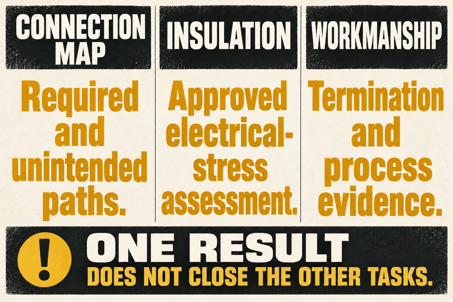
The test plan should distinguish electrical connection mapping, electrical insulation checks and mechanical workmanship. Record the approved method for each, the specimen condition, equipment requirements and disposition of failures. Do not turn an illustrative acceptance checklist into a universal test voltage or minimum resistance for every PV lead.
| Acceptance task | Bevismaterial som ska bevaras | What it does not establish by itself |
|---|---|---|
| Connection mapping | Observed paths linked to endpoint and branch references | Correct connector brand or system voltage suitability |
| Unintended-path check | Result for connections that should remain separate | Insulation performance under the required electrical stress |
| Insulation assessment | Approved method, test conditions, limit and measured result | Long-term outdoor life or complete connector qualification |
| Dimensional inspection | Measured length and breakout position against drawing datums | Electrical continuity or contact workmanship |
| Termination workmanship | Applicable process record and inspection outcome | Correct pinout throughout the complete harness |
| Marking and packing | Label content, traceability and supplied protective condition | Permission to energize or cross-mate the lead |
A continuity result should identify which path was checked, not merely state “passed.” If the approved plan evaluates resistance, record how the measurement accounts for the lead and fixture. Do not compare figures produced by different methods as though they were equivalent. Where the test is only a connection-map check, describe it honestly and avoid calling it a precise contact-resistance measurement.
An insulation test requires its own approved configuration. Establish which endpoints are included and what connected parts must be excluded or protected under the applicable instructions. Finished assemblies containing other equipment may require a different approach from loose passive leads. The buyer's role is to obtain the agreed method and result, not to improvise an instrument setting from a blog.
Make production records useful after delivery
Agree how records link the finished lead to its production lot or serial identifier. The buyer should be able to locate the released drawing, approved component list, inspection method and shipment result without searching through unrelated email photographs. The traceability level should match the procurement contract rather than being invented after goods arrive.
Ask the supplier to define which checks apply to every assembly and which are process qualification or sampled inspections. These are not interchangeable categories. A sampled mechanical assessment may support an approved process, but it should not be presented as an individual measurement of every shipped lead. The inspection plan should state that distinction plainly.
Create a change rule for cable source, connector part, contact, sealing element, termination process and endpoint labels. The supplier should identify a proposed substitution before shipment so the responsible reviewer can judge its effect. A replacement component may leave continuity unchanged while changing another acceptance requirement.
Keep nonconforming assemblies linked to their original records and correction outcome. If a path or label is reworked, agree which checks must be repeated under the approved plan. Record the final condition rather than retaining an initial failure report with no documented disposition.
Resolve a sample record by naming each missing connection
Consider a hypothetical branch order identified as lead H1 against drawing D5. D5 requires endpoint E0 to join tails T1 and T2 at one common node, with a separate path N0 to N1. These are fictional circuit identifiers, not connector contact numbers, RITOKS models or a recommended PV wiring layout. The drawing also specifies the viewing direction and distinct labels for T1 and T2. This creates an explicit target against which documents can be reviewed without guessing from connector orientation.
Supplier record C2 says that E0 to T1 and N0 to N1 have been checked under its proposed connection-map method. It supplies no entry for E0 to T2 and no result for paths that D5 requires to remain separate. The filled decision is therefore partial connection evidence, not a complete pinout pass. Keep the two reported entries, identify the missing required path, and ask the agreed reviewer to resolve the unreported separation checks. A new generic continuity-OK stamp would not answer either missing question.
Suppose revised record C3 identifies the additional required paths and separation observations against D5, and the qualified reviewer accepts its scope under the agreed plan. The connection-map field can now be closed for that specimen. If the component list still describes E0 only by a photograph, endpoint identity remains open. A correct electrical map cannot turn an unidentified connector into an approved mating partner. This is why the record should have distinct component-identity and connection-map decisions rather than one overall checkbox that hides which evidence arrived.
Now imagine a fictional supplier clarification B4 identifies a different connector part from the released bill of materials. Do not automatically accept it because C3 remains unchanged. Route the proposed substitution to the component-system reviewer and hold that changed endpoint's acceptance until its permitted counterpart and construction are established. Rejecting a substitution does not imply the recorded paths were false; it means those paths answer a different question from the supplied component identity.
Dimensions can create another independent hold. Suppose drawing D5 measures between stated connector datums, but the supplier's dimensional sheet L2 reports cable cut length only. No actual length or tolerance is assumed here. L2 has not demonstrated the required assembled reach, so the dimensional decision remains open even if the electrical map and component list are accepted. Resolve the measurement convention before treating the lead as reproducible; adding a nominal number to both documents does not make their datums equivalent.
Insulation and workmanship also retain their own outcomes under the agreed plan. A connection-map revision supplies no missing insulation method, specimen condition or acceptance result. Where a test fixture contributes resistance, record whether the result is a mapping observation or a supported resistance assessment rather than silently treating it as contact performance. These fictional records do not prescribe instrument settings, test voltages or electrical limits, and they report no actually performed factory test.
The final disposition can be narrow: H1's map accepted against D5 using C3, endpoint substitution awaiting approval through B4, dimensions awaiting a matching datum record, and other applicable acceptance tasks pending their specified evidence. Release follows the resolved scope, not the number of documents received. If a later drawing revision changes only the T2 label, investigate which marking and identification records need review; if it changes the common node, reopen the affected connection assessment. This gives change control a concrete consequence without requiring every unrelated record to be discarded.
Källor
- Stäubli. (n.d.). Cross-connections: Why preventing cross-mating is critical for PV connector safety.
- Stäubli. (2025). MA294: MC4/MC4-Evo 2 cable assembly instructions. Safety instructions, technical-data scope and cable-option sections.
- RITOKS. (n.d.). RTX-PVC PV connectors and cable assemblies. Commercial family scope, not evidence of a specific quoted lead's ratings.