
โมดูลตัวปรับกระแสแบบบริดจ์ · การเปรียบเทียบ
Half-Controlled vs Fully Controlled Rectifiers for Adjustable DC

Make phase count a separate selection field
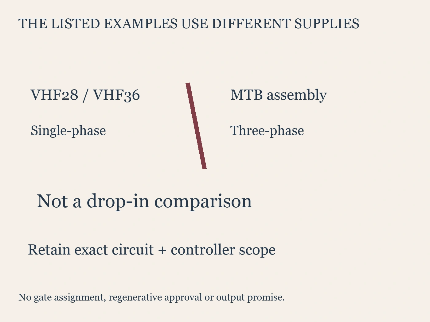
The VHF28/VHF36 semi-controlled bridge rectifier family is described as combining SCR and diode devices for controlled single-phase rectification (RITOKS, n.d.-b). The MTB38018F3FU-RF3 bridge assembly is described as a six-SCR three-phase fully controlled bridge with six gate-trigger connections (RITOKS, n.d.-a).
These actual product descriptions do not represent a same-phase-count drop-in comparison. Replacing the first architecture with the second would involve a different supply arrangement and a different firing interface. A shared “adjustable DC” application label cannot remove those differences.
Semikron Danfoss's application manual lists distinct single-phase and three-phase bridge architectures, including half-controlled and fully controlled versions. Its product-code discussion treats these as separate circuit forms rather than synonyms for a common bridge (Semikron Danfoss, n.d., section 7.2.6.1).
Start the requirement sheet with the available AC supply and the proposed bridge phase count. Then identify the controlled and uncontrolled semiconductor positions from the actual circuit. Do not infer either field from the number of large power terminals visible in a product photograph.
Compare controlled devices and the firing interface
A semi-controlled bridge contains both controlled thyristor positions and diode positions in its documented topology. A fully controlled SCR bridge has controlled thyristor positions throughout the bridge's rectifying network. The exact internal arrangement still needs to be confirmed; “SCR plus diode” alone is not an adequate gate-terminal schedule.
The practical difference for procurement is the controller scope. Determine which gate channels are required, how each channel is referenced and how the controller synchronizes with the supply. A power module can be quoted without the firing controller or without synchronization hardware, so identify those inclusions explicitly.
For MTB38018F3FU-RF3, the current page establishes six gate-trigger connections but leaves order-specific diagrams and ratings to confirmation. It does not publish a universal gate assignment. For VHF28/VHF36, the exact variant determines the internal circuit and gate interface. Neither name should be treated as sufficient installation documentation.
| พื้นที่การตัดสินใจ | Semi-controlled proposal | Fully controlled proposal |
|---|---|---|
| Supply phase count | Confirm from the exact offered circuit | Confirm separately; do not assume it matches |
| Semiconductor arrangement | Identify SCR and diode positions | Identify all controlled positions |
| Gate interface | Document each required gate and reference | Document every required gate and reference |
| Synchronization | Confirm supported supply reference | Confirm supported supply reference |
| Supplied control scope | State controller and accessories included | State controller and accessories included |
This table does not imply that a semi-controlled bridge always needs a particular universal number of channels. It directs the buyer to the exact offered circuit. The locked RITOKS examples differ in phase count, so their actual channel requirements must be reviewed as different assemblies.

Define what adjustable output must mean
An adjustable DC requirement should describe the load's operating conditions, not only a desired voltage range. Identify whether the load is resistive, inductive, capacitive or includes an active source. Record startup, steady operation and shutdown duties separately where they affect the design.
Ask the engineer to define the required output behavior over those duties. A bridge topology alone does not prove the usable adjustment range under every load condition. Supply impedance, current continuity, filtering and the chosen controller affect the complete system. Avoid promising zero-to-maximum output solely because the bridge uses thyristors.
If a calculation uses an idealized output-voltage expression, preserve its assumptions with the result. A continuous-current model should not be silently applied to a discontinuous-current operating condition. The commercial requirement can request the designer's model and its applicability without presenting a textbook expression as guaranteed product behavior.
Semikron Danfoss's rectifier-loss discussion shows different load waveforms and notes that current behavior changes with circuit inductance and phase control. This reinforces the need to retain the load and waveform assumptions when evaluating the bridge, rather than treating the firing command as the only design variable (Semikron Danfoss, n.d., section 6.1.1).
Keep energy-flow capability conditional
A customer may require only AC-to-DC power transfer, or may also require returning energy from the DC side. State that requirement explicitly. Do not describe the second case as ordinary adjustment without addressing whether the entire converter system supports the intended energy flow.
Controlled thyristor topology is only part of that assessment. The DC-side source or load, current direction, AC commutation conditions, firing controller and protective design all matter. A fully controlled bridge label does not automatically approve regeneration, reversing duty or operation under an arbitrary DC source.
Likewise, do not assume that the actual VHF28/VHF36 and MTB assemblies are interchangeable solutions for a regenerative requirement. Their offered functions and supporting documents must be evaluated individually. Where exact evidence is missing, mark the proposed energy-flow function unconfirmed instead of borrowing capability from a complete drive using a similar bridge.
Keep electrical polarity and power direction distinct in the review. Changing a commanded voltage condition, reversing load current and returning power are not identical statements. Ask the system designer to identify the intended operating modes in the actual circuit and the evidence supporting each one.
Include thermal and protection scope
Both diode and thyristor conduction create losses that must be evaluated against the actual waveforms and thermal conditions. A design with more controlled positions is not automatically cooler, more efficient or more tolerant of overload. Obtain the selected devices' forward characteristics and thermal data before making such comparisons.
The Semikron Danfoss manual gives a current-dependent average conduction-loss approach for rectifiers and explicitly treats its simplified formulas as estimates for checking a more complete calculation. It also distinguishes thermal and forward parameters given per semiconductor from module-level parameters (Semikron Danfoss, n.d., sections 6.1.1 and 7.2.6.2).
Request the intended cooling hardware, mounting requirements and operating conditions as part of the offer. If the supplier includes a baseplate or heatsink, that does not alone establish thermal suitability for the customer's cabinet and duty. Keep a supplied accessory separate from a completed thermal calculation.
Protection also requires an exact design. Identify the overcurrent, semiconductor protection and voltage-transient evidence needed for the assembly without choosing fuse sizes or snubber values from a generic comparison. Semikron's application discussion treats protection of controlled rectifier circuits as dependent on their semiconductor and circuit conditions; it does not support copying a pure-diode protection arrangement into every controlled bridge (Semikron Danfoss, n.d., section 8.4.2.3).
Build a like-for-like comparison where possible
Compare offers using the same requirement sheet. If the proposed solutions use different phase counts, label that difference prominently and evaluate the consequences for the equipment. Do not hide it in an accessories column or describe one assembly as a direct replacement before the system design has been reviewed.
| Requirement | Evidence to compare | When the comparison remains incomplete |
|---|---|---|
| Available AC supply | Phase count and exact supply conditions | One proposal assumes a different supply |
| Required DC duty | Load, operating modes and output behavior | Adjustment range stated without load assumptions |
| Firing arrangement | Controller compatibility and gate mapping | Power module offered without control scope |
| Energy-flow requirement | Supported complete-system operating modes | Regeneration inferred from bridge label |
| การออกแบบระบบความร้อน | Device losses and installation cooling conditions | Current designation used as thermal approval |
| Protection and installation | Applicable exact-model documents | Accessories listed without coordination evidence |
For a same-phase-count architecture study, ask for documented alternatives that actually use the same supply arrangement. That can isolate the effect of controlled versus uncontrolled device positions more clearly. The current RITOKS examples should retain their actual single-phase and three-phase identities rather than being rewritten to create an artificial comparison.
The bridge rectifier module category is a useful commercial starting point for those inquiries. It groups related rectifier families, but it is not evidence that their terminals, controllers or installation requirements match.
Prepare the RFQ and acceptance record
Attach the supply and load requirements, desired operating modes and available drawings. Identify whether the request covers the bridge alone or a complete assembly with firing control, synchronization, cooling and protection. Ask the supplier to separate confirmed exact-model facts from information awaiting the customer's system design.
The final comparison should say why the proposed topology was selected and which alternatives were rejected for a specific reason. “Fully controlled is better” is not a useful decision record. A supported result might instead identify a supply mismatch, an undocumented control interface or an unconfirmed energy-flow requirement.
At handover, preserve the selected order code and the revisions of the circuit and controller documents. Distinguish document review from physical installation checks and authorized operating verification. A technically coherent quotation does not prove the completed equipment was assembled or commissioned as designed.
Common topology questions
Is half-controlled always single-phase?
No. Half-controlled describes the mixture of controlled and uncontrolled semiconductor positions, not a universal supply phase count. The actual VHF28/VHF36 page describes single-phase rectification, while other manufacturer catalogs document additional architectures. Use the exact offered circuit to establish phase count and gate requirements.
Is a fully controlled bridge a complete DC power supply?
Not automatically. The commercial scope may omit firing control, synchronization sensing, cooling or protective devices. Request those inclusions explicitly. The topology describes the rectifying network; it does not establish every component and verification needed for an installed adjustable supply.
Can the two listed RITOKS families replace each other directly?
Not on the basis of their current descriptions. One is described as a single-phase semi-controlled family and the other as a three-phase six-SCR assembly. Their supply, firing and installation interfaces differ. Any substitution requires an actual system redesign or compatibility assessment supported by exact documentation.
Does fully controlled mean regenerative operation is approved?
No. The complete operating mode needs evidence for the DC side, supply commutation, controller and protective design. Keep regenerative or reversing functions unconfirmed unless the exact assembly and system documentation support them. A bridge label is not sufficient approval for that duty.
Conclusion
Compare half-controlled and fully controlled rectifiers through the actual supply, load, gate interface and operating requirements. Keep phase count separate from controlled-device topology and avoid describing the present single-phase and three-phase examples as direct substitutes. A clear scope and evidence record makes the selection useful without inventing adjustment, regeneration or thermal capability.
แหล่งอ้างอิง
- RITOKS. (n.d.-a). MTB38018F3FU-RF3 three-phase fully controlled SCR bridges. https://ritoks.com/products/mtb38018f3fu-rf3-three-phase-fully-controlled-scr-bridges/
- RITOKS. (n.d.-b). Semi-controlled bridge rectifier modules. https://ritoks.com/products/semi-controlled-bridge-rectifier-modules/
- Semikron Danfoss. (n.d.). Application manual power semiconductors (AB509142199100en-000205, sections 6.1.1, 7.2.6 and 8.4.2.3). https://assets.danfoss.com/documents/latest/530447/AB509142199100en-000205.pdf