
DC Power Protection · Technical Explainer
Battery Distribution Box Circuit Maps: Separate Independent Branches

Quick answer
A battery distribution box's input and output counts do not establish its internal topology. Map every external port to its documented internal node, protective device and destination. Confirm which branches are independent and which share a connection before interpreting the enclosure as a battery combiner. Use the exact ordered configuration's drawing and bill of materials.
The useful buying deliverable is a port-to-node register tied to a controlled schematic. It should distinguish observed hardware, supplier descriptions and approved circuit relationships. This guide provides document-review questions, not terminal wiring instructions or permission to parallel batteries. Actual system design, protection and installation remain with qualified personnel and the relevant equipment manufacturers.
Start with the exact configuration, not the enclosure label
An enclosure can have several cable entries without connecting their conductors to one common bus. Conversely, several visibly separate terminals can share an internal node. Counted openings, breakers and labels therefore answer different questions. Ask the supplier for the circuit drawing of the exact order before deciding what the box connects.
The RITOKS TPBAT4-B7 four-way battery protection box is presented as a pictured four-input, four-output configuration. Its published page requests an exact battery one-line diagram and internal fuse or breaker bill of materials. The input/output count is a procurement starting point, not evidence that all inputs are paralleled internally.
Keep the representative product scope visible. The page separates the pictured configuration from broader project-specific family offerings. A quotation must name the supplied configuration and document revision. Do not use a family photograph as proof that a different order has the same internal arrangement or transfer a higher-voltage claim from another configuration.
Give the requested circuit a short purpose statement. For example, the project may require separate battery branches to remain distinct between named sources and conversion equipment. That statement defines a requirement to review; it does not establish that the offered box already satisfies it. Compare the requirement against the actual drawing, not the product title alone.
Assign stable identities to every external port
Label each external connection in the review record before describing its relationship to other ports. The identifier should refer to a terminal or connection group on the supplier's drawing, with the conductor roles stated. Avoid names such as “left input” that become ambiguous when the enclosure orientation changes.
Keep the equipment identity separate from the box-port identity. A battery bank, inverter interface and spare connection can each have their own designation. Record which equipment is intended at each port and whether the assignment is confirmed or proposed. An unassigned port should remain unassigned rather than receiving an invented load merely to complete the table.
Also distinguish a port from a circuit. One connection group can include several conductors, while one circuit can pass through multiple physical terminals and protective devices. Use the schematic's actual references to explain the relationship. The reviewer should not have to reconstruct the circuit from photographs taken at different angles.
| Port-register field | Information to request | Ambiguity it removes |
|---|---|---|
| External identifier | Exact drawing reference and physical marking | Which connection the record concerns |
| Conductor role | Roles stated in the approved system drawing | Whether a port count was mistaken for a conductor count |
| Intended equipment | Named battery, converter or other approved destination | Which source or load belongs to the connection |
| Internal node | Node reference on the exact schematic | Whether connections are common or separate |
| Protective-device path | Relevant device reference and stated function | Which circuit the device is intended to protect |
| Configuration status | Proposed, confirmed or unresolved with revision | Whether the relationship is approved or only assumed |
This is an original purchasing worksheet, not a completed TPBAT4-B7 terminal schedule. The public family page does not supply every terminal identity or node relationship. Obtain those details for the exact supplied assembly and preserve the manufacturer's identifiers rather than substituting a convenient numbering scheme.
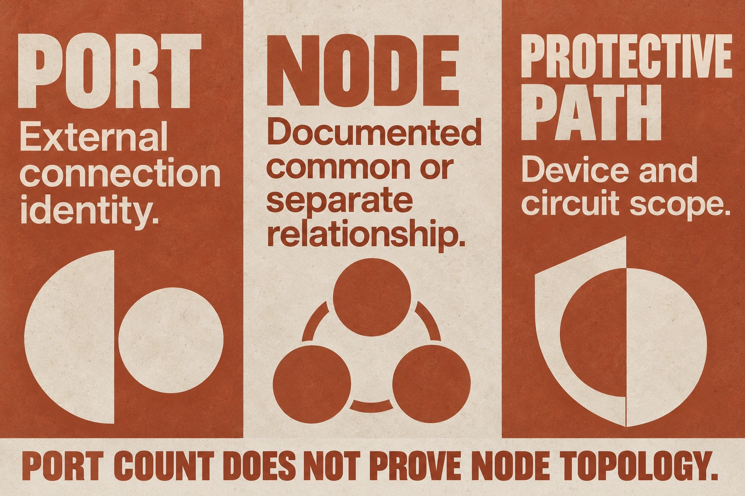
Read common nodes separately from protective-device paths
A shared node is a defined electrical connection in the circuit drawing. A protective device is a component in a particular path with its own documented function. Do not assume that separate protective modules prove source independence, or that a busbar description proves every port is on the same node. Follow the complete drawing and ask for any missing relationship.
For each branch, trace the documented route from its external connection to the intended destination. Record whether the route meets a shared node and where that occurs relative to the relevant devices. The buyer is requesting a circuit explanation, not deciding a fuse placement or breaker arrangement from an illustration.
If the supplier uses the word independent, ask what it means in the offered configuration. It might refer to individually identified outputs, separate switching functions or circuits that do not share the relevant internal nodes. These are different statements. Replace the general adjective with the actual circuit relationship the project needs to preserve.
The TPBAT family page describes internal busbar and DC protective components at a general level, while asking buyers to verify the exact bill of materials. It does not establish a complete node map for every custom assembly. Keep “busbar listed” separate from “this port connects to that node” until the drawing documents the latter.
Use a node register to settle disagreements between a quotation and a drawing. If the quotation says separate branches but the drawing shows a common connection, identify the exact references and ask for clarification. Do not choose whichever document seems more convenient. The supplied assembly, circuit drawing and acceptance description need to agree.
Preserve the battery system's source boundaries
Connecting a box between batteries and power-conversion equipment makes the source arrangement part of its specification. Identify the batteries or banks involved and the system's permitted relationships. A box with the required number of inputs is not approval to connect otherwise incompatible battery sources together.
Victron's Lithium Smart installation manual separates parallel, series and series/parallel arrangements, and provides configuration-specific battery and protective requirements. That is an example of manufacturer-specific source boundaries, not a topology approval for TPBAT4-B7 or an arbitrary battery combination. Use the instructions governing the actual installed sources. Victron Lithium Smart installation manual
Ask the responsible designer to identify all equipment that can energize a connection in the approved system. The review may need to consider charging and discharging states where they actually exist. Do not label every port permanently as a source or load solely because an early enquiry called it an input or output.
Where sources must remain separate, record the boundary as a requirement and request evidence that the proposed node arrangement preserves it. Where a shared connection is intended, request the corresponding source-compatibility and protection review. Neither outcome follows from the box name. Keep an unresolved relationship visible until the responsible parties determine it.
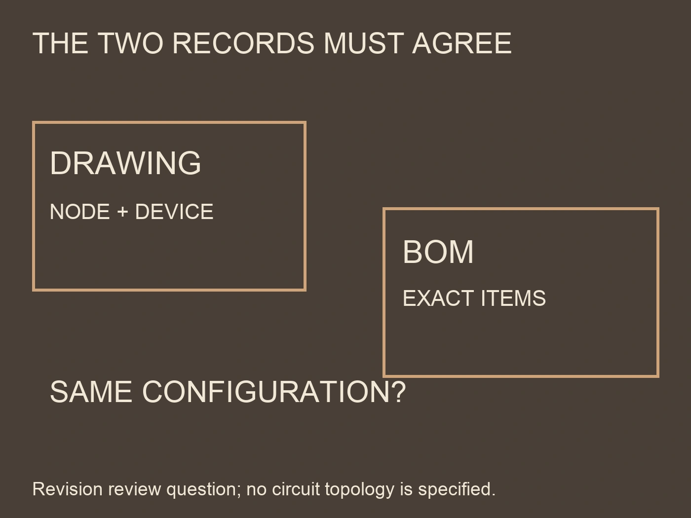
Check the drawing against the bill of materials
The drawing identifies circuit relationships; the bill of materials identifies the exact components used to realize them. Both documents should describe the same configuration. A generic list of DC breakers does not establish each device's order code, function or application conditions, and an accurate component list alone does not reveal every connection.
Request cross-references between device tags on the drawing and item references in the bill of materials. Ask which items are fixed in the order and which remain subject to confirmation. A substitution should be reviewed against the circuit duty, installation arrangement and relevant documentation, not accepted because its outline fits the enclosure.
| Document comparison | Question to resolve | Evidence that closes the question |
|---|---|---|
| Port schedule versus schematic | Do the same external identities appear? | Controlled references for every intended connection |
| Schematic versus device list | Is each protective function tied to an exact item? | Device tag and order-reference cross-map |
| Quotation versus node map | Are shared and separate relationships described consistently? | Revised agreement naming the actual topology |
| Source drawing versus enclosure drawing | Does the assembly preserve the required battery boundaries? | Responsible designer's configuration review |
| Delivered markings versus documents | Can a reviewer identify the supplied connection points? | Approved inspection record for the actual assembly |
| Later change versus original approval | Which relationships or components changed? | Dated revision and affected review items |
The table does not specify acceptance limits or claim the offered assembly has passed a test. It identifies the records needed before making that decision. Actual inspection and electrical verification should follow an agreed plan for the exact assembly, with results retained separately from the expected circuit map.
Count branch groups after a hypothetical node change
Consider a fictional order whose external schedule contains four input groups I1 to I4 and four output groups O1 to O4. The arithmetic gives eight external groups, not eight conductors or eight independent circuits. Each group may contain the conductors identified by its own drawing. The names here are teaching identifiers, not TPBAT terminals or a wiring prescription. At this stage, the port count says nothing about which source relationships remain separate.
Suppose schematic R1 documents four separate source-branch groups G1 to G4. Within each group it identifies an input, its protective-device path and the intended output; between the relevant groups it shows no common source connection in the assessed state. The completed review can record four documented separate branch groups, subject to the actual drawing's scope. This does not prove galvanic isolation, safe work boundaries or protection suitability. Those broader claims require their own definitions and evidence.
Now imagine revision R2 adds a documented common connection between the relevant G1 and G2 source nodes while retaining all eight external groups and their labels. On this simplified relationship count, the original four separate groups become three: the combined G1/G2 group, G3 and G4. The count is four minus one, not eight minus one, because the question concerns source-group relationships rather than visible ports. It does not imply all inputs now share one bus or that every conductor in either group is common.
If the requirement was four separately maintained source relationships in that state, R2 no longer demonstrates that requirement. Calling its four outputs independent does not resolve the conflict if independent merely means individually protected or individually labelled. The buyer should return the specific common-node change to the designer and supplier. There may be a valid reason to revise the system requirement, or the assembly may need another documented arrangement, but relabelling the ports cannot undo an electrical relationship.
Suppose the protective-device tags remain P1 to P4 after the change. Four listed protective paths still do not restore four separate source groups. Each device needs its actual circuit duty reassessed where the new source relationship changes the current through it or another path. Conversely, documenting separate source groups would not by itself establish that P1 through P4 provide adequate protection. The filled record keeps topology and protective capability as distinct findings instead of letting one count stand in for the other.
This example also explains a delivery discrepancy. A photograph can still show four entries, four exits and four protective modules under either revision. Receiving inspection needs the accepted configuration and supported verification, not only matching counts. Preserve R1's requirement, R2's changed node relationship and the responsible decision together. No actual TPBAT internal topology, terminal assignment or permission to parallel battery sources is asserted by this hypothetical group calculation.
Conclusion
A clear battery distribution specification connects each port identity to a documented node and protective path. It also identifies the source boundaries the assembly must preserve. Approve the topology from consistent configuration records, then assess the exact components and inspection evidence. Port counts help organize the enquiry; they do not decide which batteries or branches may be connected together.
แหล่งอ้างอิง
- RITOKS. (n.d.). TPBAT4-B7 four-way battery protection box. Representative configuration and information needed for exact assembly selection.
- Victron Energy. (n.d.). Lithium Smart Battery manual: Installation. Configuration-specific battery and protection requirements; no TPBAT topology approval implied.