
DC Power Protection · Technical Explainer
PV Y-Branch Connectors: Check Parallel Current and String Protection
Quick answer
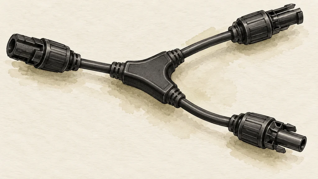
A PV Y-branch connector creates a current-merging point. Check the current through each branch leg and the common path, the exact inverter's permitted input arrangement, and the fault-current paths that could feed another string. A connector's current rating is not automatic string overcurrent protection, and a Y adapter is not a DC load-break device.
Use the actual module, cable, branch assembly and inverter documents to decide whether the proposed connection is suitable. Trace each protective device to the fault path it can interrupt. Do not approve the design from connector appearance, a generic parallel-string count or a fuse placed somewhere in the common output.
This guide defines a design-review and procurement task. It does not provide a universal wiring layout, fuse rating or live connection procedure.
Mark the merging point on the actual circuit
Start with an annotated circuit drawing showing each string, both polarities, the branch components and the common cable to the inverter. Label the exact string identities and connector references rather than drawing an unidentified Y symbol.
Distinguish a single branch assembly from a network of nested branches. If another branch is added downstream, the common-path duty and the number of electrically connected sources may change even though the original connector remains in place.
Record whether the branch is supplied as a moulded connector, a prepared cable assembly or another construction. The relevant conductor, contact and junction information must match that construction. The visual shape does not prove an internal fuse, blocking device or particular current capability.
Stäubli's MA250 instructions provide a specific parallel-connection example and require correct string interconnection. Its connector data and installation requirements belong to that Stäubli system; the example is not a universal protected-array layout. Stäubli, MA250 branch-connector instructions.
Separate normal branch current from common-path current
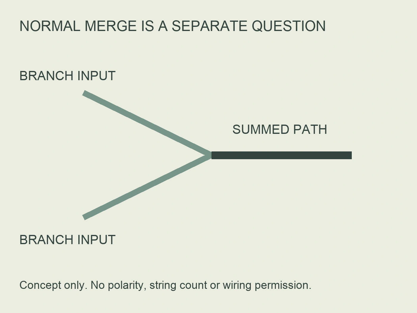
In normal generation, the branch legs carry their respective string contributions while the shared path carries the combined contribution at the merging point. The design-current basis must account for the actual PV source and relevant operating conditions under the applicable project rules.
Do not apply one string's current to every part of the assembly. Check the common output cable, its contacts and downstream connection separately. If the supplier provides only one headline assembly rating, ask which paths and conditions it covers.
Also distinguish operating current from short-circuit current. The inverter may document different limits for those quantities. A normal-load calculation below one operating limit does not complete the short-circuit or reverse-current review.
For the RITOKS RTX-PVC branch-assembly enquiry, request the selected Y configuration, circuit layout, cable and mating references, and applicable current information. The page's separate panel reference does not rate every Y branch, cable pair or extension.
Identify the fault backfeed path separately
Normal current directed toward the inverter is not the only relevant path. A faulty parallel string can receive current from other connected strings. That exposure may involve the faulty string's modules, cables and connectors rather than only the common inverter cable.
SMA's historical Reverse Current technical note explains how a fault reducing a string's voltage can allow other parallel strings to feed it, potentially causing damaging heating. The note covers a Sunny Mini Central context; only this qualitative fault-path principle is used here. Its simplified string-count conclusions and historical built-in protections are not current global design rules. SMA, Reverse Current technical information.
Have the responsible designer identify relevant fault locations and contributions using the actual circuit. The number of physical sockets is not enough to determine which strings are electrically connected together or which source contributions remain possible.
Do not assume module bypass diodes provide string reverse-current blocking. They are different functions. If another device is relied on to block or interrupt a fault path, identify it and obtain the exact supporting design evidence.
Keep inverter inputs and MPPT groups distinct
An inverter input connector is a physical interface. An MPPT grouping is part of the inverter's internal electrical and control architecture. They should not be treated as interchangeable labels without the manufacturer's diagram.
Obtain the exact inverter model's permitted string and input arrangements. Record any shared limits, required settings or restrictions. Connecting more strings through Y branches does not create additional independent trackers or automatically increase an input's permitted duty.
SMA's Sunny Boy Smart Energy connection instructions illustrate model-specific permitted input pairing and simultaneous per-input and combined short-circuit limits. Those exact pairings, counts and numerical relationships cannot be applied to another inverter. The useful lesson is to check both local and combined limits in the selected manual. SMA, PV connection options.
If the inverter documentation does not clearly authorise the proposed arrangement, resolve it with the manufacturer before ordering branch assemblies. A connector that physically fits does not establish an electrically permitted input configuration.
Collect a path-specific input register
Use the following original register to make the proposed branch arrangement reviewable. It is a planning aid, not a completed calculation or a published RITOKS inspection record.
| Circuit element | Evidence needed | Distinct question to answer |
|---|---|---|
| Individual strings | Exact module references, string configuration and current data | What can each string supply under the assessed conditions? |
| Branch legs | Cable, contact and assembly identity | What operating and fault duties affect each leg? |
| Common path | Combined-current basis and exact cable/connector data | What changes after the merging point? |
| Module protection | Manufacturer overcurrent and reverse-current information | Which limits and protection requirements apply to the module? |
| Inverter interface | Exact input/MPPT diagram and current limits | Is the proposed arrangement permitted at each and shared boundary? |
| Protective devices | Location, selected reference and applicable characteristics | Which assessed fault paths actually pass through the device? |
Give each missing item an owner. A supplier can provide assembly information, while the system designer must relate it to module and inverter requirements. Do not fill a gap with the rating of an unrelated connector or a familiar rule from another project.
Do not equate maximum series-fuse rating with reverse-current withstand
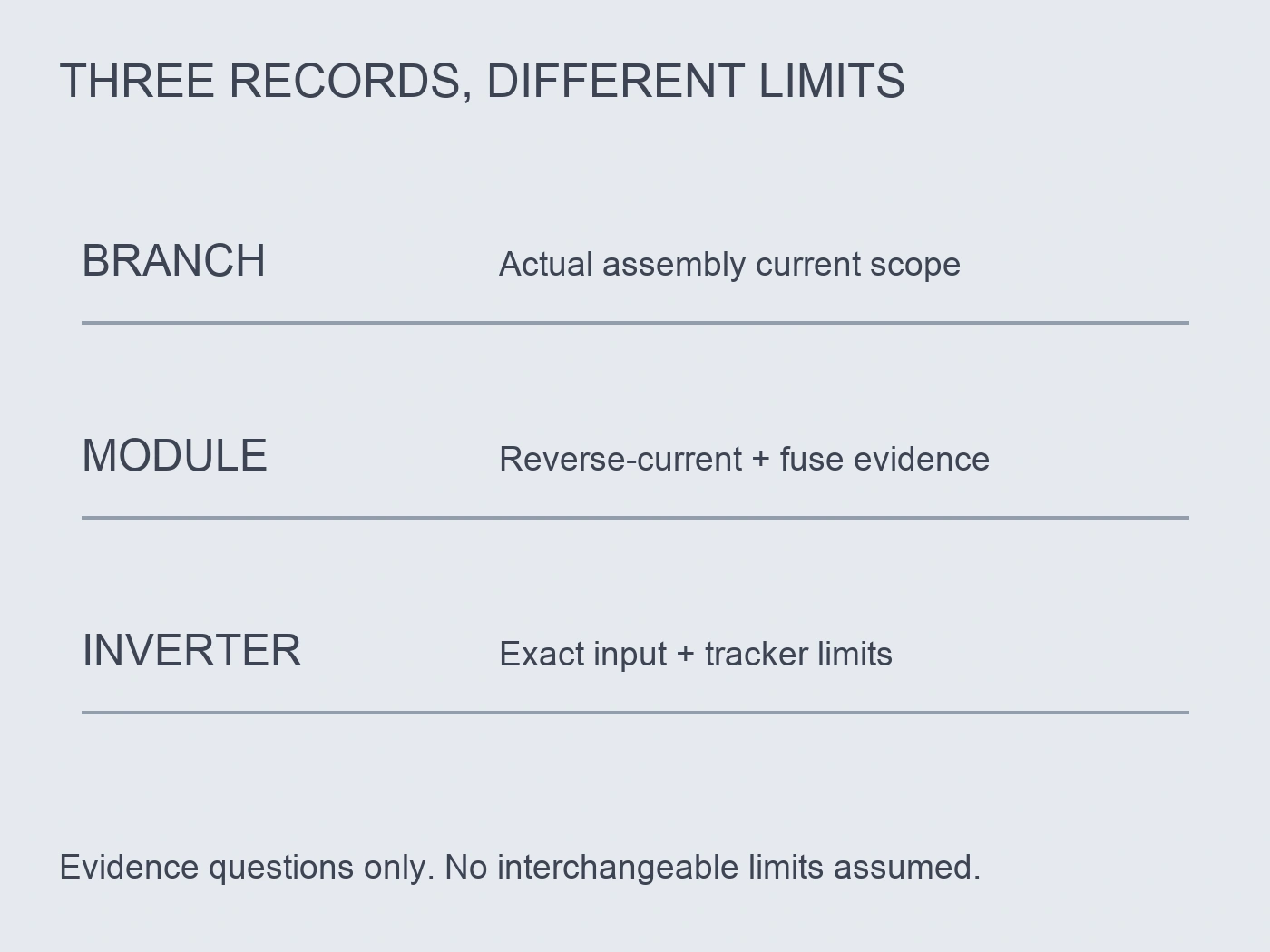
Obtain the module manufacturer's exact protection information and terminology. A maximum series-fuse rating identifies a protective-device constraint; it should not be silently relabelled as a guaranteed continuous reverse-current withstand value.
If the documentation provides a relationship between fields, retain that specific explanation. If it does not, request clarification rather than inventing equality or an allowable exposure time. A fuse's eventual operation also needs its applicable characteristic, not just its current marking.
SMA Benelux's December 2018 technical tip separates inverter-facing current questions from module reverse-current questions. Its historical local calculations are not adopted here. It is useful as a reminder to obtain the module protection data and evaluate the correct equipment boundary. SMA Benelux, string-fuse technical tip.
Keep cable and connector limits in the review as well. Satisfying one module constraint does not automatically protect all components of the backfed branch.
Match protection location to protected scope
For each proposed fuse or protective device, mark its position and follow the assessed fault-current path through the drawing. A device helps only where the relevant current traverses it and its documented characteristics are suitable for the duty.
A fuse on the common inverter path should not automatically be credited with protecting a fault current circulating between parallel branch legs. The review must establish the actual path and intended protected equipment. Conversely, a string protective device should not be assumed to resolve every inverter input limitation.
This is why the protection-location decision and branch-current decision belong on the same reviewed drawing. Listing a connector and several fuses on the purchase order does not establish that the circuit has the intended protection.
| Review case | Path to examine | Evidence required before concluding |
|---|---|---|
| Normal generation | String legs merging into common output | Applicable path ratings and combined-current assessment |
| Faulted string | Contributions from other connected sources into that leg | Actual fault assessment and module/cable/connector limits |
| Inverter-facing duty | Common connection and permitted input grouping | Exact inverter operating and short-circuit requirements |
| String protection | Current path through the selected device | Location, DC application data and protection characteristics |
| Common-path protection | Fault scope downstream of the merging point | Documented protected scope, not assumed coverage of all legs |
| Proposed expansion | Revised merge points and electrical source grouping | Updated assessment rather than reuse of the original approval |
The table describes questions to resolve, not universal fuse-placement instructions. The responsible designer determines the applicable protection arrangement and acceptance basis.
Source the exact fuse system if protection is required
Where the approved design calls for a gPV fuse, request the exact fuse reference and supporting application data. Confirm the voltage, current, applicable fault characteristics and the compatible holder arrangement using the supplied documentation.
Цей RITOKS 10×65 mm PV fuse-link family та 10×38 mm PV fuse-link family are different dimensional and voltage families. They are alternative sourcing references, not interchangeable links or a verified holder pairing. Do not transfer one family's data to the other.
Neither page establishes a string-specific selected fuse current or a completed branch-protection result. The engineer still needs the exact module, circuit and protective-device evidence. Avoid selecting a larger fuse solely to prevent unwanted opening without reviewing its protection consequences.
If an integrated fused branch assembly is proposed, require documentation of that exact construction. An ordinary Y connector does not acquire that function merely because a separate fuse is sold alongside it.
Include routing and safe access in the release package
Electrical review should identify the approved assembly's mechanical and environmental installation requirements. Cable tension, twisting, bend requirements, water exposure and thermal conditions can affect the selected connector arrangement. Use its exact instructions rather than adopting another manufacturer's numerical spacing.
MA250 includes mechanical, thermal and cable-management requirements for its branch components. This supports requesting installation information as part of the branch assembly package, not treating the Y component as an unconstrained free-standing junction.
The SMA connection example explicitly says Y adapters must not be used to interrupt the DC circuit. Follow the selected equipment's proper disconnection procedure through competent personnel. Do not demonstrate branch performance by unplugging a connector under load or deliberately creating a string fault.
Retain the accepted string/input map, component schedule and protection review with the order. If another string or replacement module family is added, review the changed common currents, fault paths and inverter boundaries before treating it as a minor connector change.
Work through a branch change without turning a sum into approval
Consider a hypothetical drawing B2 with strings S1 and S2 merging before a shared inverter connection. In one deliberately simplified normal operating snapshot, S1 contributes 12 A and S2 contributes 11 A, giving 23 A in the common path. These are invented currents for teaching the path distinction, not module short-circuit data, design-current multipliers or RTX-PVC ratings. The filled operating record assigns 12 A to one leg, 11 A to the other and 23 A to the shared segment; it does not repeat one leg's value throughout the assembly.
Suppose fictional assembly document A3 states a 25 A limit for the common path under conditions that match this hypothetical snapshot. The arithmetic comparison is 23 A against 25 A, a difference of 2 A. That difference is not a protection margin, a temperature allowance or approval for the proposed PV system. If A3 does not cover the leg contacts, the leg assessment remains open despite the common-path comparison. The reviewer can accept that this single operating comparison is below its assumed documented limit while withholding the wider assembly decision.
Next, the supplier offers a third string S3. In another fictional normal snapshot it adds 10 A, making the common contribution 33 A. Under the same assumed 25 A condition, that proposal exceeds the common limit by 8 A. This is a specific reason to decline the unchanged common-path proposal, not a universal rule against three strings. A different documented common arrangement might change the result, but adding a socket or relabelling the original Y assembly cannot change the evidence already associated with A3.
The fault review is a separate record. Assume the drawing owner identifies a possible path from the healthy parallel sources into S1 upstream of the common output protective device F0. The unresolved question is whether a suitable device actually interrupts that assessed path. F0's presence on the equipment list is not enough; if the identified path does not traverse it, the reviewer cannot credit F0 with that protection. No backfeed magnitude, fuse current or operating time is supplied by the normal 23 A sum, and this hypothetical path description is not an installation layout.
Inverter response V4 may then permit a named input grouping while leaving its short-circuit-current documentation incomplete. That resolves an architecture question but not the outstanding current duty. Likewise, module response M2 might publish a maximum series-fuse field without documenting the assumed reverse-current exposure. The record should preserve both completed and open findings. Treating all three responses as one generic supplier confirmation would lose which party and document can actually close the remaining question.
The decision can therefore reverse for a reason other than normal current. A proposal below the assumed common-path limit may still be held because its inverter grouping or fault protection is unsupported. Conversely, adequate protection documentation does not cure the 33 A common-path exceedance in the expanded snapshot. Return each revision to the changed boundary: A3 for assembly paths, V4 for the exact inverter arrangement, M2 for module protection inputs and the circuit owner for fault routing. All identifiers, limits and observations here are fictional; none selects a fuse or authorises a real array. The useful output is a filled, path-specific decision with named unresolved evidence, rather than an apparently reassuring total.
Література
- Stäubli. (2025, December). MA250: MC4 branch-connector instructions, Index e. Manufacturer example only. Accessed October 2, 2026.
- SMA Solar Technology. (n.d.). Reverse Current: Sunny Mini Central generator configuration, Version 1.0. Historical source; qualitative fault-path explanation only. Accessed October 2, 2026.
- SMA Solar Technology. (n.d.). Sunny Boy Smart Energy: PV connection options. Exact-model input example, not universal wiring instructions. Accessed October 2, 2026.
- SMA Benelux. (2018, December). Nood aan stringzekeringen?. Historical/local protection-boundary discussion; numerical rules not transferred. Accessed October 2, 2026.