
DIN Rail Energy Meters · Technical Explainer
Charge and Discharge Energy on a DC Meter: Check Register Direction

Quick answer
Do not assign charge and discharge labels to a DC energy meter's registers until the exact model documentation defines their direction. Review the measurement boundary, current and power sign conventions, cumulative-energy definitions and communications data map together. A familiar register name or an RS485 connection does not prove the required bidirectional measurement capability.
The useful deliverable is a direction-mapping record: what physical energy exchange the project means by charge or discharge, what the selected meter calls it, and which documented data field represents it on the receiving platform. Keep this record separate from a commissioning result. Expected behavior needs manufacturer evidence; actual behavior needs a safely obtained, configuration-specific observation.
This guide is for procurement and integration teams working on battery and other DC circuits. It does not publish a DC02NC register address, provide wiring instructions or prescribe an energized test. Where an exact register table or bidirectional definition is missing, leave the mapping unconfirmed rather than borrowing another manufacturer's numbers or conventions.
Start with the named measurement boundary
First identify what the meter is intended to observe. A battery connection, a charger output and a particular DC load can be different measurement boundaries. A platform label such as “charged energy” is incomplete without identifying the battery or circuit to which the label refers.
Write the purpose before creating data points. For example, the project might require energy received by a named battery and energy delivered by that battery, separately accumulated. That requirement is not automatically satisfied by a meter that measures one charger branch. Confirm the system drawing and exact meter capability with the responsible designer.
Keep the location record tied to the data record. If the meter is moved to a different branch, the same register address can represent a different physical exchange. The integration may continue to return plausible numbers while the old label becomes misleading. Record both the measurement-point identity and the hardware identity, and reopen the mapping when either changes.
Цей RITOKS DC02NC shunt-input DC energy meter family lists DC voltage, current, power and energy, with communication options depending on the model. Its public family description does not provide an exact forward/reverse register map or establish every variant's bidirectional behavior. Request those documents for the proposed order code before committing to a platform mapping.
Separate instantaneous signs from cumulative counters
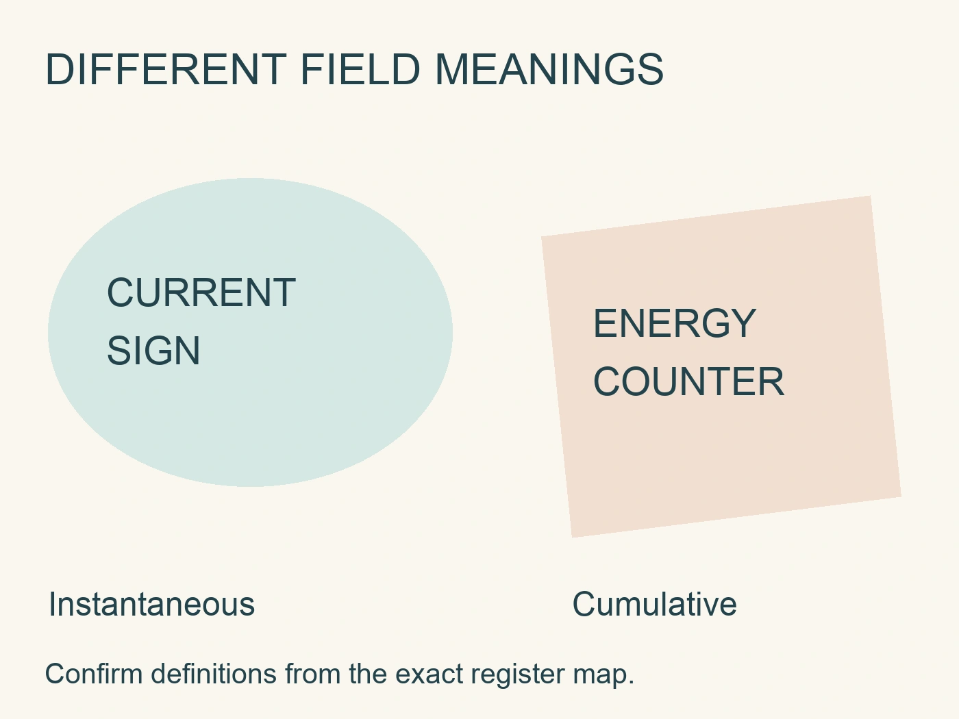
A signed current value describes direction under the meter's documented convention at the observation time. A cumulative-energy field describes an accumulated quantity under its own definition. The two are related through the instrument's documented behavior, but they are not interchangeable data points.
Victron's SmartShunt operation manual gives a bounded example: its battery-monitor current convention identifies positive current as entering the battery and negative current as leaving it. Its history section separately defines charged and discharged energy in kWh. This demonstrates the value of reading both definitions; it does not establish DC02NC signs, addresses or counter behavior.
Do not infer a lifetime energy total from a current snapshot. Likewise, an accumulated value can remain unchanged between two reads without proving that a branch has no exchange: the instrument's update and resolution definitions must be known. Document the expected behavior from the exact meter manual rather than adding a platform rule to make the display look active.
| Data item | Definition to obtain | Interpretation to avoid |
|---|---|---|
| Поточний | Direction reference, sign convention and unit | Positive always means battery charge on every meter |
| Потужність | Measurement boundary, sign convention and unit | A familiar sign convention from another device applies here |
| Charge energy | Exact physical direction and accumulation definition | The word charge proves whole-battery coverage |
| Discharge energy | Exact physical direction and accumulation definition | A reverse counter automatically matches the project's meaning |
| Total or net energy | Manufacturer's stated calculation and scope | Every total equals charge minus discharge |
| Displayed platform value | Documented source field and conversion | A friendly label validates the source semantics |
Use these definitions to explain the data in ordinary language. The phrase “energy delivered by the named battery according to the reviewed meter map” is more useful than an unexplained “E2” field. Keep the manufacturer's original field name available in the integration record so later reviewers can trace the translation.
Build the register-to-platform mapping record
For a communicating meter, obtain the register document that matches the exact model and supported configuration. Record its revision and the hardware or firmware applicability stated by the manufacturer. A table found for a similar case size or family name is not sufficient evidence of the selected variant's data layout.
Each platform point needs more than an address. The record should identify the field definition, unit, data representation and any documented scale factor. If a field occupies multiple registers, retain the manufacturer's representation and ordering instructions. Do not decide these from a value that happens to look plausible during a single read.
Separate the raw acquired value from the human-facing value. A platform may apply a conversion or label after reading the meter. Both steps need traceability. If the raw field is correct but the conversion is wrong, changing the physical sensing arrangement would address the wrong problem and could introduce unnecessary installation changes.
Ask the supplier to mark missing information against the same mapping record. “Modbus supported” describes a communications option, not a complete integration answer. The source register must be documented as the required energy quantity, and its meaning must survive the proposed conversion and dashboard naming.
The article intentionally contains no example register addresses or decoding constants. Those would need exact-model evidence that is not supplied by the public family page. A blank, clearly assigned field is safer and more useful than an invented register that later becomes part of a production data collector.

Check counter behavior before comparing periods
An energy comparison between two times requires a clear definition of the counter, not just two numbers. Obtain the exact meter's documented reset, persistence and rollover behavior, where relevant to the requested reporting period. Do not assume that an accumulated field is lifetime, nonresettable or preserved through every power interruption.
Retain the time and configuration associated with each observation. A counter difference can be misleading if a device was replaced, a reset occurred or a mapping changed between the reads. Those events should remain visible in the integration history rather than being hidden by a convenient zero or an unexplained discontinuity.
The receiving platform also needs a policy for missing observations. Ask how it distinguishes an unavailable reading from a valid zero. A communications failure does not establish zero charge or discharge energy. Keep data availability separate from the electrical condition and avoid treating an incomplete reporting interval as a proven no-activity interval.
| Reporting question | Exact evidence needed | Status without that evidence |
|---|---|---|
| Which direction does the counter represent? | Model-specific field definition and measurement reference | Direction unconfirmed |
| Can it be reset? | Documented reset behavior and access scope | Reset behavior unconfirmed |
| What survives a power interruption? | Exact product persistence specification | Persistence unconfirmed |
| How is a period difference formed? | Approved counter interpretation and event handling | Reporting rule unresolved |
| What happens when data is unavailable? | Receiver and integration handling specification | Availability behavior unresolved |
| Does replacement preserve the series meaning? | Hardware-change and mapping record | Continuity review required |
These are evidence questions, not claims that the DC02NC provides any particular reset or persistence feature. Mark a requirement as unsupported if the proposed configuration cannot document it. Do not silently replace that requirement with a platform calculation that has not been reviewed.
Plan an authorized direction verification
Before commissioning, agree the expected observations using the exact manufacturer definition and the approved system purpose. Identify the known operating state, the meter fields to observe and the platform points to compare. Qualified personnel must choose any physical test method under the relevant site and equipment procedures.
The integration record should distinguish expected results from actual results. A table prepared from the manual is not evidence that the installation behaved as expected. Save actual observations with the configuration, time, responsible person and applicable procedure, and retain any unresolved difference rather than replacing the observation with the expected value.
Where a direction mismatch appears, examine the documented measurement reference and the data mapping together. Do not immediately reverse conductors, change polarity settings or invert a platform value. The reviewer needs to establish which layer is inconsistent and whether any proposed change is permitted by the exact equipment instructions.
Also avoid using a counter total from before the test as a current-direction proof. It can contain earlier operation under a different setup. The verification plan should define which observations can establish the question at hand and what other information is required. This article supplies the questions, not a safe test sequence or acceptance threshold.
A conditional integration example
Suppose a project requests separate battery charge and discharge totals, and a supplier offers a DC meter with RS485. The first quotation states only “DC energy.” That is insufficient to accept the two platform points: neither the exact supported directional counters nor their meanings have been established.
The buyer requests the order code, applicable register table and direction definitions. If the documents establish separate accumulated directions, the integrator can compare those definitions with the named battery boundary and draft the mapping. If only an unspecified total is documented, the two-counter requirement remains unresolved. No addresses or capabilities are invented in this example.
Now suppose the supplier's forward direction refers to a different physical reference from the platform's existing charge label. The naming issue needs a documented translation, not a silent assumption that forward means charge. The design and integration owners should approve the relationship before any dashboard communicates the value to operators.
Finally, if the meter is replaced or its supported map changes, the record should identify the change and the applicable observation period. Retain the previous mapping for earlier data and verify the new one. The outcome is traceable energy semantics, not a claim that two unrelated devices are interchangeable or that a battery has achieved a particular efficiency.
Questions to resolve in the RFQ
Does RS485 prove bidirectional energy measurement?
No. Communication support and measurement capability are separate questions. Obtain exact-model evidence of the required directional values, their definitions and the supported data fields. The public family page alone does not settle those details.
Does positive current always mean charging?
Only use the convention stated for the exact instrument and measurement reference. Another manufacturer's example can illustrate the need for a sign definition without supplying it for the proposed meter. Align the platform label with the reviewed physical boundary.
Can I rename forward and reverse registers as charge and discharge?
Only after documenting the relationship between those manufacturer definitions and the project's battery boundary. Similar words are not evidence of identical meaning. Keep the original field name and the approved translation in the mapping record.
What should accompany the order?
Provide the measurement purpose, approved circuit reference, required directional quantities, reporting-period expectations and receiving-system requirements. Request the exact meter configuration, shunt compatibility documents and applicable register map. Keep missing capabilities visible before technical acceptance.
Література
- Victron Energy. (n.d.). Manual—SmartShunt: Operation, sections 5.2 and 5.5.2. Manufacturer manual.