
Current Shunts for DC Measurement Systems · Comparison
Low-Side vs High-Side Shunt Measurement: Check Common-Mode Limits
Draw the reference potentials before choosing the location
A shunt produces a small differential voltage, so it is tempting to assume that a matching millivolt meter can be connected wherever the shunt fits. That skips an important question: what are both sensing terminals' potentials relative to the receiving instrument's reference? A small difference between two terminals can exist while both sit far from that reference.
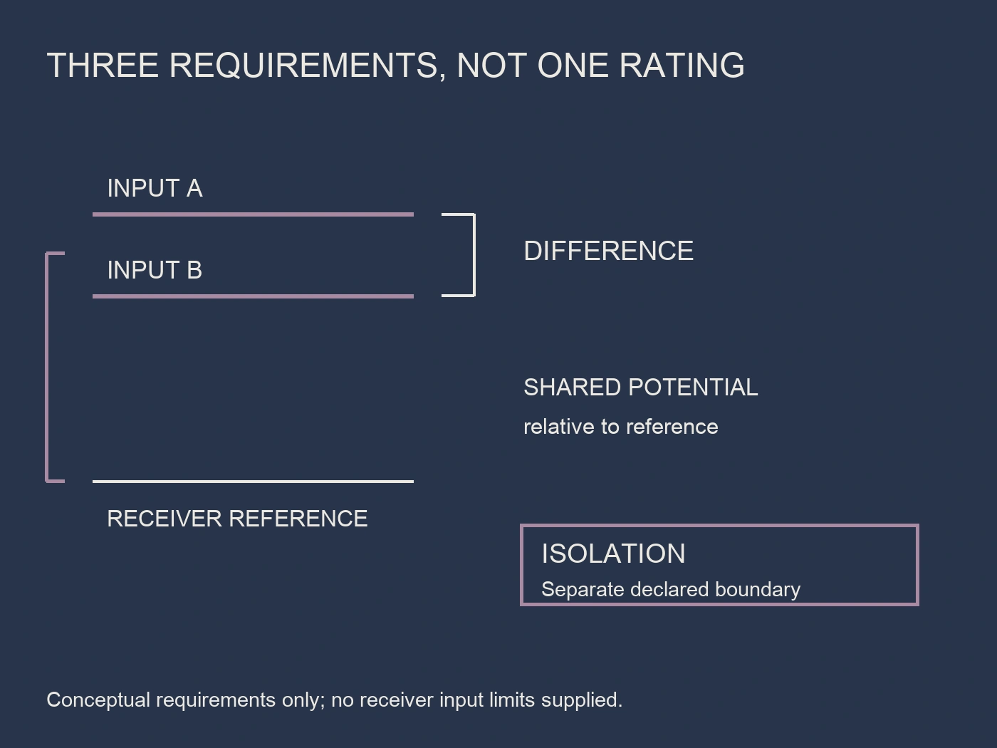
Low-side versus high-side shunt measurement is therefore a measurement-chain decision, not simply a mechanical placement choice. Establish the current path, reference potentials, receiver input limits and any required isolation boundary before accepting a location. Differential input range, common-mode range and isolation are separate requirements.
This guide helps DC-system and instrumentation teams prepare that comparison. It is not a wiring procedure or permission to change a grounded or floating system. The deliverable is a potential-reference map and a bounded acceptance record showing what the selected instrument actually supports. The location name alone cannot close those questions.
Keep differential voltage, common mode and isolation distinct
Differential voltage is the difference between the two sensing inputs. Common-mode voltage describes their shared potential relative to the receiver's defined reference. For a simple conceptual input pair, it is represented by the average of the two input potentials relative to that reference. Actual allowable conditions must come from the receiving equipment's documentation.
Цей FL-2-75 shunt family lists a 75 mV rated-output family with model-dependent current selection. That output is not an input-to-earth rating, a common-mode specification or proof of galvanic isolation. Do not use it as evidence that the complete instrument can be connected at an arbitrary DC-bus potential.
Isolation asks a different question: which parts of the measurement chain are electrically separated, and under what declared conditions? A common-mode-capable input does not automatically establish an isolation barrier. Conversely, an isolation declaration needs a defined boundary; a broad statement that an instrument is “isolated” may not identify the relationship between its sensing input, supply, communications and accessible interfaces.
Record these requirements in separate fields. A completed differential-range comparison can coexist with an unresolved common-mode or isolation question. Keeping the gap visible is more useful than approving a proposed connection because one number matches the shunt's rated output.
Compare low-side and high-side arrangements in their stated circuit
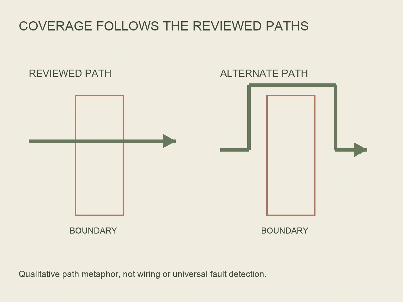
Texas Instruments' application brief SBOA165 discusses low-side sensing in a grounded return path. It identifies the return-reference shift caused by the shunt and the possibility that an alternative fault-current path bypasses it. Its high-side example moves the measurement into the supply path, with a corresponding receiver common-mode requirement.
Use these as topology-specific considerations, not universal verdicts about every DC installation. A low-side arrangement may be acceptable when its reference shift and current-path coverage are addressed. A high-side arrangement still needs evidence that the receiving circuit tolerates the input conditions and that the intended current passes through the selected shunt location.
High-side placement does not guarantee that every fault in an installation will be visible. The actual sources, branches and return paths determine which currents cross the measurement boundary. Have the designer identify the paths under review rather than assuming one shunt observes all possible conditions.
The following original comparison map describes review questions, not ratings or a recommended connection for a particular RITOKS meter.
| Review question | Grounded low-side example | High-side example |
|---|---|---|
| Reference relationship | Shunt may shift the monitored return relative to reference | Inputs may sit near the supply potential relative to receiver reference |
| Current coverage | Identify return paths that do or do not cross the shunt | Identify supplied branches that do or do not cross the shunt |
| Receiver suitability | Check actual input conditions, not only nominal proximity to ground | Check documented common-mode and other applicable input limits |
| Isolation requirement | Define it independently of placement | Define it independently of common-mode capability |
| Acceptance | Review the exact circuit and instrument | Review the exact circuit and instrument |
Define the reference in a floating DC system
“Low side” should not be read as “safe earth potential” in an unearthed or floating arrangement. The negative conductor's potential relative to a meter reference or protective earth is not established by the word negative. Record how the receiver is referenced and how that reference relates to the DC circuit under the relevant conditions.
Ask the designer to identify the grounding arrangement, instrument supply relationship and applicable operating or fault cases. Do not assign an arbitrary earth reference to make the comparison convenient. A drawing that labels only positive and negative may still omit the very relationship needed to assess the input.
Where the reference is unclear, request clarification before deciding the shunt position. Neither a millivolt output designation nor a matching current range answers it. The measurement-chain assessment should identify both sensing-input potentials relative to the receiver reference, with the document and conditions that establish them.
This is not a request to measure hazardous potentials casually with an unspecified instrument. The required information should come from controlled design evidence and, where needed, an authorized verification plan. Keep documentary uncertainty separate from permission to perform physical work.
Check the exact receiver rather than a generic amplifier example
Цей DC02NC external-shunt-input DC energy meter provides a relevant product family for an inquiry, but its public listing does not establish a high-side common-mode or complete isolation guarantee. Request the selected configuration's permitted shunt position, reference connections and input limitations before treating it as suitable for the proposed topology.
TI's examples describe particular current-sense amplifier capabilities. They do not establish that the DC02NC implements the same input architecture, powered-down tolerance or isolation. Do not transfer a TI voltage range to the meter, nor claim compatibility between the two RITOKS families solely because both refer to an external shunt measurement.
The receiver review should address normal operation and other applicable conditions identified by the designer. Ask about startup, powered-down inputs and transients where they matter. Keep allowable operating limits separate from absolute maximum conditions and do not convert a withstand statement into a promised valid measurement range.
Include instrument power and connected interfaces in the reference map. A communications connection can introduce a relationship that a simplified shunt-only sketch omits. Ask the manufacturer to identify the relevant boundaries and instructions, rather than assuming that a separate power supply or communication feature makes the entire chain isolated. Shunt heating is a separate review; see estimating DC shunt loss without assuming a safe temperature.
Create a potential-reference map for the proposed arrangement
Use a controlled drawing to identify the selected shunt's two sensing points, the receiver's stated reference, its power supply and connected interfaces. Name the current path being measured and the branches considered. The purpose is to make the comparison auditable, not to draw an unapproved installation.
Keep the following fields adjacent to the applicable manufacturer evidence. This original worksheet does not prescribe terminal names or state that the selected products provide every listed capability. If the shunt signal feeds a battery monitor, see why coulomb counting can drift.
| Map field | Необхідні докази | Question to close |
|---|---|---|
| Differential signal | Exact shunt output and receiver input declaration | Is the intended signal within the documented measurement range? |
| Input-to-reference potentials | Circuit cases and receiver common-mode limits | Are both inputs in the supported conditions? |
| Receiver supply/reference | Manufacturer connections and project drawing | What establishes the input reference? |
| Isolation boundary | Applicable declaration naming the separated circuits | Which boundary is actually provided? |
| Current coverage | Defined paths and reviewed branches | What current can this placement observe? |
| Other conditions | Applicable startup, power-off or transient documentation | Which cases remain unresolved? |
For example, the shunt-output comparison is documented, but the receiver's high-side input limits have not been supplied. Record the differential requirement as addressed within its stated scope and common-mode suitability as evidence pending. Do not collapse the result into “compatible” or declare the meter defective because the documentation is incomplete.
In another case, the input limits are available, but a project drawing adds a separate return path after review. Preserve the prior acceptance and identify the changed current-coverage question. The electrical input may remain within range while the measurement no longer represents the intended total. Those are different findings and need separate treatment.
Keep measurement coverage separate from protection claims
A current reading can inform monitoring, but selecting high-side or low-side placement does not automatically create a certified fault-protection function. If the project relies on a measurement for protection, the required performance, response and architecture must be assessed within that separate design scope. No such function is established by this article.
Likewise, a plausible reading does not prove input suitability or isolation. A commissioning comparison should follow its authorized method and retain the configuration, conditions and responsible reviewer's findings. It must not replace missing manufacturer limits with a single successful observation.
If a proposed change moves the shunt, changes the meter supply or adds a connected interface, reopen the affected reference-map fields. The same model numbers do not necessarily mean the same measurement boundary. Retain the earlier document as history so future reviewers can see why a previously accepted arrangement was reconsidered.
Close the topology decision with defined evidence
Send the supplier the proposed circuit and exact instrument configuration, identifying the intended shunt location and reference relationships. Request permitted placement, differential input range, common-mode conditions and the applicable isolation declarations. Ask the project designer to resolve the current-path coverage and other required circuit cases.
The final decision should identify the arrangement actually reviewed, not simply say “high side is better” or “75 mV matches.” Approve the defined measurement chain only when its required evidence is complete. Where it is not, retain a precise open question: signal range, reference potential, isolation boundary or current coverage. That makes the next engineering step clear without inventing a capability.
Source notes
Sources inspected 1 October 2026. Reference maps and comparison tables are original editorial tools, not installation instructions or compatibility approvals.
- RITOKS FL-2-75 shunt family: rated-output family; no isolation inference.
- RITOKS DC02NC meter family: external-shunt-input product context; exact placement and receiver limits require confirmation.
- TI SBOA165: low-side and high-side sensing: grounded return-reference, bypass-path and common-mode considerations. No TI device range or interface capability assigned to RITOKS.