
DC Power Protection · Technical Explainer
PV Extension Cable Length: Balancing Voltage Drop and Connector Count
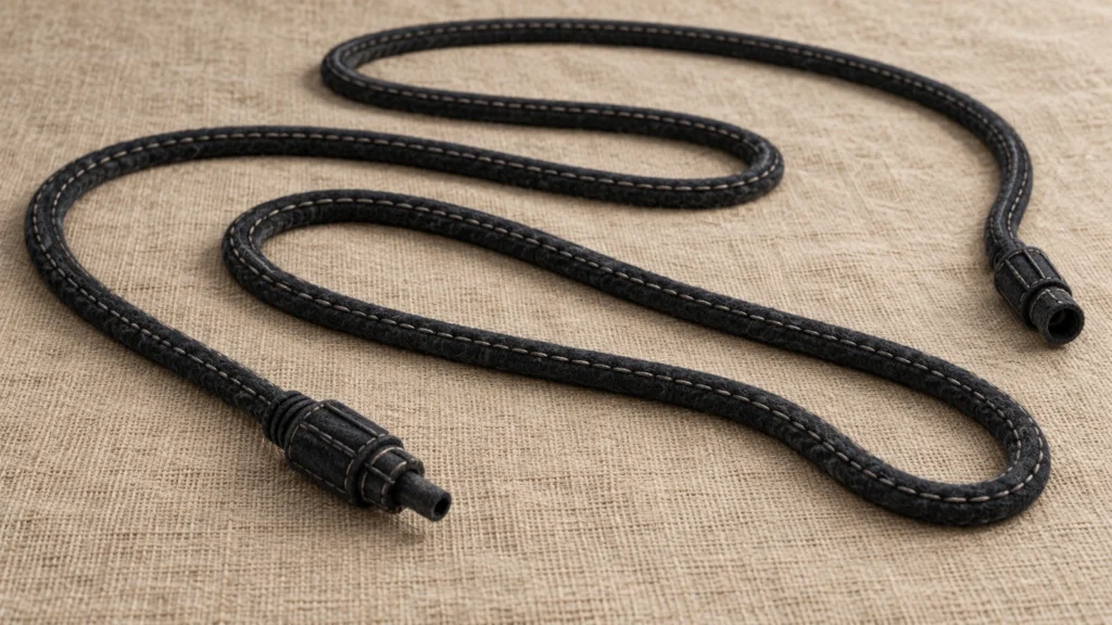
Quick answer
Specify PV extension cable length from the actual positive and negative conductor routes, not the straight-line distance between equipment. Evaluate each segment using its documented resistance, relevant conductor temperature and current. Include connection interfaces within the assessment boundary, with supported contact data rather than an invented loss per connector.
A shorter assembly with fewer joints may simplify the circuit, but it still needs the correct cable, mating components, installation allowances and maintenance access. There is no universal extension length or voltage-drop percentage that approves every PV circuit. Agree the project acceptance basis with the responsible designer before turning a route estimate into an order.
This guide provides a procurement input register and comparison method. It is not a cable-sizing approval or a procedure for testing an energised PV string.
Define what the proposed extension includes
An extension quotation can describe one conductor, a positive-and-negative pair, or several assembled pieces. Establish the scope before comparing lengths or prices. A pair labelled with one length does not automatically tell the engineer the total electrical path.
Mark the extension's start and end interfaces on the circuit drawing. Identify which original module leads, branch assemblies, equipment tails and internal connections sit outside that supplied item but remain inside the electrical assessment. Otherwise, a calculated result for the new cable alone can be mistaken for the full string-to-inverter result.
Keep the extension separate from a branch assembly. A branch joins current paths; an extension lengthens a path. Where both occur, mark the merge point and assign the correct current scenario to the common section. Do not give every cable segment the same current merely because it appears on one drawing.
For the RITOKS RTX-PVC extension and cable-assembly enquiry, request the selected extension configuration, cable designation, endpoint references and length convention. Separate panel-reference information on the product page does not establish the resistance or rating of every extension variant.
Record positive and negative routes independently
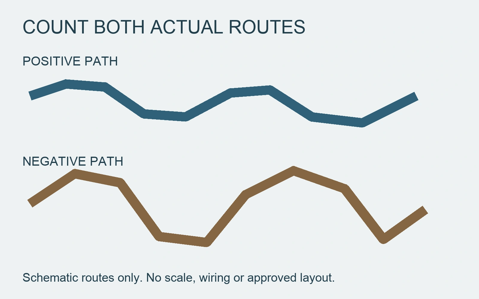
Measure the intended conductor route, including necessary entry paths and purposeful installation slack. The positive and negative runs may have different lengths. A roof-to-inverter distance is not necessarily either conductor's actual route.
On the drawing, distinguish one-way equipment distance, each conductor's cut length and the sum of the relevant conductor lengths. If the supplied calculation input already represents the complete outgoing-and-return path, do not multiply it by two again.
Record how the assembly length is measured. The purchasing specification should say whether it refers to cable cut length, an assembled end-to-end dimension or another clearly defined measurement. Connector bodies and cable preparation make vague length descriptions difficult to reproduce.
Use route changes to update the register. A revised equipment position, alternative cable tray or additional branch can change both the length and electrical boundary. Preserve the original and revised drawing references so the supplier is not building from an obsolete sketch.
Request conductor resistance with its temperature basis
Cable section alone is not a complete resistance input. Obtain the exact cable manufacturer's DC resistance information, its units and reference temperature. Identify whether the figure is a maximum specification, a typical value or a measured result for the supplied assembly.
Resistance depends on the conductor and its temperature as well as length and section. PVsyst's documentation explains these relationships and explicitly includes the outgoing-and-return path in its DC example. Its sample results and illustrative targets are not universal PV design limits. PVsyst, cable resistance and ohmic losses.
Ask how the proposed operating-temperature resistance is obtained. Use a supported manufacturer relationship or other justified engineering basis. Do not treat ambient temperature, conductor temperature and a cable's maximum permitted temperature as interchangeable inputs.
Prysmian's Prysun photovoltaic cable sheet illustrates the documentary distinction: its electrical table separates reference-temperature conductor resistance from higher-temperature voltage-drop data and installation-dependent current information. Those data describe that cable, not RITOKS assemblies. Prysmian Colombia, Prysun photovoltaic cable data sheet.
Before applying any drop coefficient, confirm its length basis and units with the source. A coefficient already representing a circuit pair cannot safely be combined with an additional assumed return multiplier. An unresolved unit or boundary question belongs on the review list, not inside a finished result.
Build a segment register before calculating
The following original register separates supplier data from project decisions. Complete one entry for each materially different cable segment and connection boundary, rather than using one generic cable description for the entire route.
| Register field | Information to record | Why it changes the comparison |
|---|---|---|
| Segment identity | Positive or negative path, start/end points and drawing revision | Establishes what length and resistance belong to the path |
| Routed length | Actual conductor length, allowance and measurement convention | Avoids one-way versus loop ambiguity |
| Cable identity | Manufacturer reference, conductor material and nominal section | Ties the resistance evidence to the proposed cable |
| Resistance basis | Value, units, reference temperature and maximum/typical/measured status | Prevents incompatible data from being treated as equivalent |
| Operating case | Segment current and supported conductor-temperature basis | Defines the conditions behind the assessed drop and loss |
| Connection boundary | Mated interfaces and terminations included in the result | Locates contact data and possible omissions |
| Acceptance owner | Designer, specification reference and unresolved items | Separates procurement completeness from engineering approval |
Where different cable sizes or temperatures occur along a path, retain separate rows. Where a common section carries merged current, retain its own operating case. A spreadsheet that hides these distinctions behind one total length is difficult to audit or revise.
Use an explicit electrical boundary for the comparison
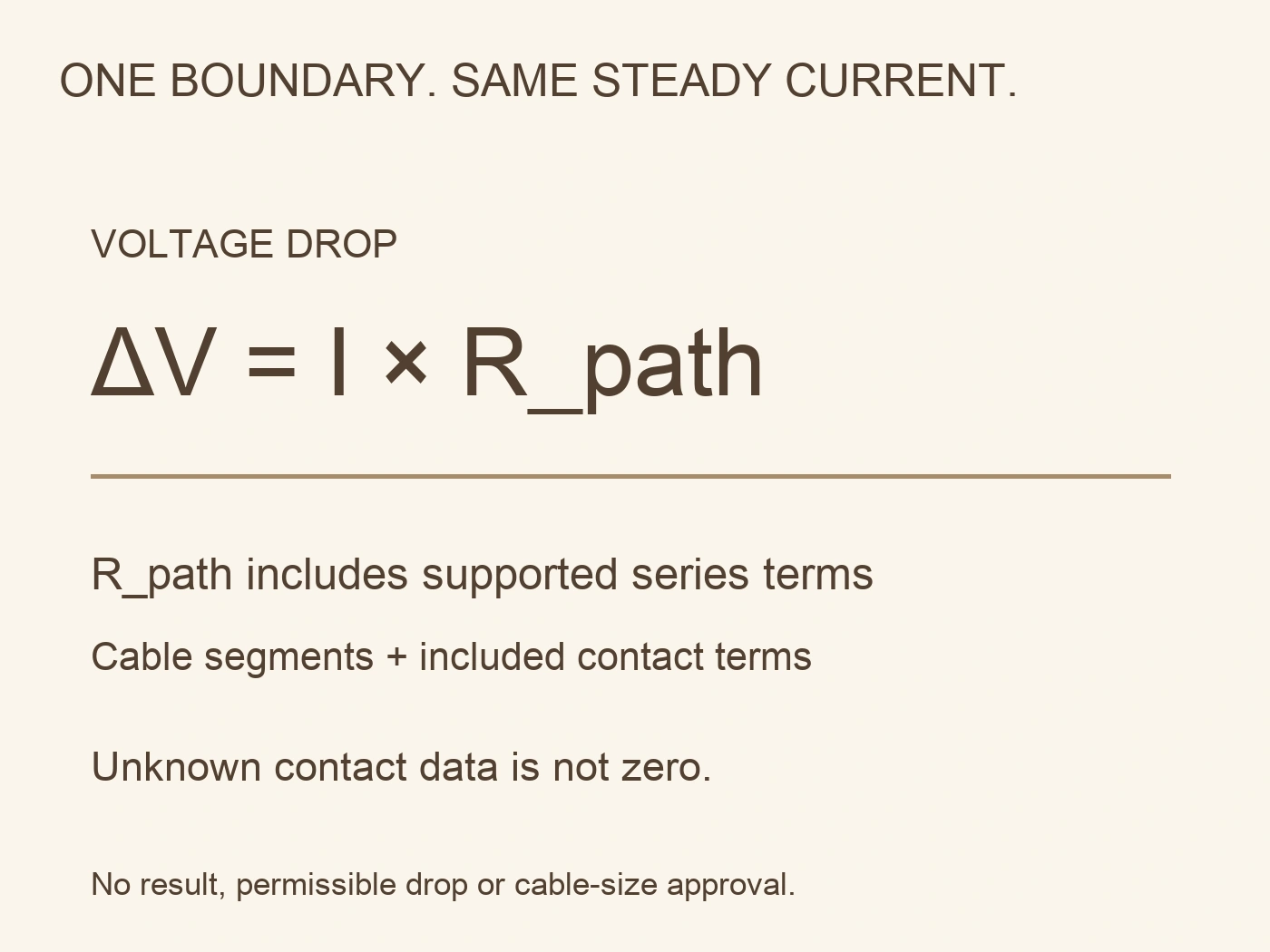
For a defined DC path carrying the same steady current throughout, the basic relationships are:
ΔV = I × R_path
P_loss = I² × R_path
Here ΔV is voltage drop in volts, I is current in amperes, R_path is the resistance within the stated assessment boundary in ohms, and P_loss is instantaneous resistive power loss in watts. These relationships do not supply missing resistance or choose an acceptable result.
For a uniform cable segment, resistance can be obtained from a supported resistance-per-length value multiplied by that segment's length, with consistent units. Sum the relevant segment resistances and documented series contact terms without counting any term twice.
Where segments carry different currents, such as before and after a branch merge, assess their losses individually and sum those losses for the chosen system boundary. Do not apply one branch current to the whole network's resistance. Define the specific path before describing a voltage drop.
Sandia's PV Performance Modeling Collaborative identifies cabling, connections and fuses as potential wiring-loss contributors. It also explains that different cable lengths or sizes in parallel strings can contribute to unequal voltage drops and mismatch. Sandia PVPMC, DC wiring losses.
A result at one operating condition is not automatically an annual energy-loss estimate. Keep that distinction visible when commercial comparisons discuss efficiency or savings. Do not invent a yearly benefit from one current and temperature point.
Count connections to identify evidence, not a fixed penalty
List each mated electrical interface on both polarities. Include the relevant termination boundaries, and state whether a supplied assembled-resistance result already covers them. Counting plastic connector housings is not the same as identifying every resistive connection in the path.
Ask for the exact contact or assembly data and the conditions under which it was obtained. A value for another connector family, a new contact under a different test condition or a mismatched mating combination is not evidence for the proposed assembly.
If contact resistance is undocumented, mark the contribution as unknown. Do not assign zero or invent an equal resistance for each connector to make the calculation look complete. The engineer can decide what additional supplier evidence or controlled assessment is necessary.
Fewer joints can reduce the number of interfaces requiring specification and inspection. That does not prove an arbitrary reduction in voltage drop or make a long preassembled cable automatically preferable. Compare the complete proposals rather than ranking them solely by connector count.
Compare a purpose-made assembly with chained extensions
Consider a longer purpose-made assembly and several shorter stock extensions as distinct proposals. Each needs a route, connection schedule, cable identity and installation scope. The comparison should expose missing evidence before selecting a purchase option.
| Decision item | Purpose-made assembly question | Chained-extension question |
|---|---|---|
| Route fit | Is the specified finished length appropriate for the approved route? | Do the available lengths create excess cable or force an unsuitable route? |
| Connection schedule | Which endpoint and internal terminations are included? | Which additional mated interfaces are introduced on each polarity? |
| Електричні докази | Does resistance information cover the exact cable and assembly boundary? | Can each segment and added interface be supported consistently? |
| Технічне обслуговування | Can the intended equipment be accessed without cable strain? | Are intermediate interfaces accessible and protected as required? |
| Change control | Can the supplier reproduce the drawing and endpoint references? | Are all extension and mating references fixed, rather than substituted? |
| Release decision | Has the designer accepted the complete proposed arrangement? | Has the extra-joint arrangement been assessed, not merely assumed equivalent? |
This table is a purchasing review aid, not a claim that either option always wins. Commercial availability and replacement strategy can be recorded alongside the technical assessment, but neither overrides component instructions or the accepted design.
Keep voltage drop separate from cable suitability
A satisfactory voltage-drop assessment does not independently approve current-carrying capacity, insulation, fault protection, mating compatibility or environmental installation. Increasing conductor section may change the cable diameter and termination requirements as well as resistance.
Likewise, reducing length must not remove required bend allowance, support, strain relief or maintenance access. Do not pull a cable tight to achieve a smaller spreadsheet number. Apply the selected cable and connector instructions to the actual route.
The release file should contain the agreed assembly drawing, conductor lengths, exact cable and endpoint references, evidence register and designer's acceptance conditions. Record unresolved contact or temperature inputs openly. Supplier confirmation of order details and engineering approval of the circuit are different decisions.
Qualified personnel must plan any installation or verification under the applicable safe-work requirements. Do not assess an extension by unplugging it under load or making improvised resistance measurements on an energised string.
Compare two filled route records and preserve the unknown contacts
Consider two hypothetical extension proposals for the same defined steady-current loop. Route A has a 20 m positive conductor and a 24 m negative conductor, for 44 m of conductor in total. Route B has 20 m and 30 m, for 50 m. Assume solely for this teaching example that both use a documented operating-temperature resistance of 0.004 ohm per metre and carry 10 A throughout the assessed loop. These are invented inputs, not a cable specification, a reference-temperature conversion or a permissible installation length.
A's cable-only resistance is 44 multiplied by 0.004, or 0.176 ohm. Its cable-only drop is therefore 1.76 V and its instantaneous cable loss is 17.6 W. B's corresponding values are 0.200 ohm, 2.00 V and 20.0 W. The difference is 0.24 V and 2.4 W at this one assumed current and temperature. No second return multiplier is applied because both conductor routes are already included. Neither result includes contact terms or establishes annual energy loss, circuit suitability or a project acceptance threshold.
The initial purchasing preference might favour A's shorter route, but the record must distinguish a cable-only comparison from a finished-assembly one. Suppose B's fictional evidence package R4 additionally covers a total series contact contribution of 0.005 ohm within this exact assessment boundary. B's total becomes 0.205 ohm, giving 2.05 V and 20.5 W. A's contact contribution remains undocumented. Its total is 0.176 ohm plus that unknown contribution; counting fewer housings does not supply the missing value.
The crossover is explicit: an A contact total below 0.029 ohm would keep A's assessed resistance below B's hypothetical 0.205 ohm total. At exactly 0.029 ohm the totals match; above it the resistance comparison reverses. This subtraction is a sensitivity result, not an allowable contact-resistance limit or an invitation to measure an energised string. R4 and its contact value are fictional evidence for arithmetic only. A real supplier would need supporting data with the same assembly boundary, specimen condition and measurement basis before such a comparison could be relied on.
Route fit can reverse the preference independently of that resistance result. If the shorter A drawing omits the purposeful allowance needed for approved maintenance access, its electrical advantage does not justify pulling the cable tight. The designer should revise A's route and recalculate the resulting length rather than delete the allowance from the purchasing drawing. B may be preferred if its reviewed arrangement provides the required access and its complete evidence is available, even while a cable-only spreadsheet still favours A.
Finally, suppose an alternative A cable offers a lower documented resistance but has a different outer diameter. Retain the improved electrical calculation as one finding and reopen its sealing, contact and routing applicability as different findings. An apparently better drop number is not authority to substitute the cable inside an existing connector assembly. The filled decision names each route revision, records cable-only and complete-boundary results separately, and leaves unresolved inputs visible. That is the practical value of the calculation: it identifies exactly which evidence could change the choice without presenting an invented value as a manufacturer result.
Література
- Sandia National Laboratories, PVPMC. (n.d.). DC wiring losses. Technical modelling discussion. Accessed October 2, 2026.
- PVsyst SA. (n.d.). Cable resistance, voltage drop, and ohmic losses. Basic DC relationships; example targets not adopted as universal limits. Accessed October 2, 2026.
- Prysmian Colombia. (n.d.). Cable Prysun Fotovoltaico. Exact-cable data presentation only; numerical values not transferred. Accessed October 2, 2026.