
Voltage Transducers for Industrial Monitoring · Technical Explainer
Line-to-Line or Line-to-Neutral Voltage: Define the Transducer Input
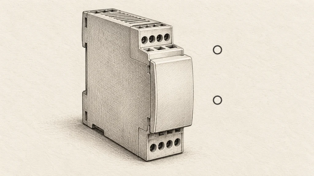
Quick answer
Define an AC voltage transducer input by naming both measurement nodes on the actual system drawing. A line-to-line quantity uses two identified phase conductors; a line-to-neutral quantity uses an identified phase and the system neutral. Do not choose the connection from terminal count, a familiar nominal voltage or the output signal alone.
Confirm the system topology, grounding arrangement, available neutral, intended voltage quantity and exact transducer's permitted input conditions. Keep measured input, auxiliary supply and controller-facing output separate. The selected range must be supported for that application, including relevant input-to-earth and insulation requirements, not merely numerically larger than the expected reading.
This guide prepares an input-definition and procurement record. It does not provide terminal wiring instructions or a live-panel test procedure.
Name the two nodes before choosing a range
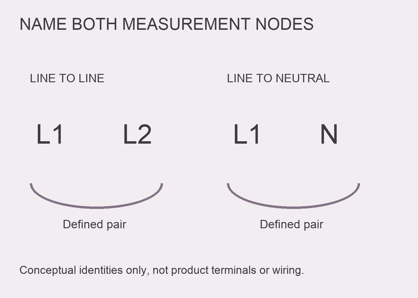
Write the intended measurement as a specific pair, such as L1–L2 or L1–N, using the project's actual conductor identifiers. These are conceptual examples, not instructions to connect a particular product.
If the requirement says phase voltage, ask which two points it means. If it says supply voltage, identify whether the user wants a particular line-to-line quantity, a line-to-neutral quantity or several separately defined channels. Those descriptions should not remain ambiguous in an order or controller tag.
Locate the pair on the single-line drawing and identify the equipment boundary. A measurement at an upstream bus and one at a downstream machine input may refer to different points even when the same nominal voltage is written beside them.
The completed specification should state the measured nodes and quantity explicitly. An input-range label without that definition does not explain what the output represents.
Do not infer the reference from two input terminals
Both a line-to-line measurement and a line-to-neutral measurement involve two named points. Having two voltage input terminals therefore does not prove that the second terminal is neutral or that every two-wire application has the same electrical reference.
Schneider's EasyLogic PM1125H/PM1110H direct-connect section distinguishes two-wire line-to-neutral and two-wire line-to-line configurations, along with several wye and delta arrangements. Its numerical limits and settings belong to those meters, not to a RITOKS transducer. The example demonstrates why the system definition must precede the product connection decision. Schneider Electric, direct-connect voltage limits.
Obtain the exact transducer's terminal diagram and application description. Do not rename a terminal from its position on the housing or a diagram belonging to another manufacturer. Where the supplier description is unclear, request written clarification tied to the order code and drawing revision.
Establish topology and the actual neutral
Record the system phase arrangement and grounding description from verified project documents. Identify whether the proposed location actually provides the neutral needed for the intended quantity. Do not invent a neutral because a controller label expects a line-to-neutral reading.
Neutral and protective earth have different roles. A protective-earth conductor, PLC common or output return is not automatically the required measurement neutral. Similarly, an auxiliary supply return does not define the reference for the high-voltage measured input.
Grounded, resistance-grounded and ungrounded arrangements can impose different considerations on the measurement application. The relevant question is whether the selected device is permitted for the actual system and stresses, not whether a diagram from another project looks similar.
Have the responsible designer resolve the reference and suitability evidence. This article intentionally does not provide a generic neutral/earth link, substitute connection or field wiring remedy.
Use an input-definition register
The following original register helps procurement and controls staff ask for the same measured quantity. It is not a completed electrical design or a list of universally required terminal connections.
| Definition item | Project information to record | Supplier evidence to request |
|---|---|---|
| Measurement nodes | Exact conductor/node identifiers and drawing location | Permitted configuration for that input pair |
| Cấu trúc hệ thống | Phase arrangement, grounding and neutral availability | Relevant application restrictions and terminal diagram |
| Intended quantity | AC voltage meaning and required interpretation | Measurement principle and supported waveform conditions |
| Operating input | Nominal quantity and relevant expected range | Exact selected range and documented input limits |
| Input-to-earth conditions | Designer's applicable system/environment basis | Insulation, overvoltage and installation suitability information |
| Controller signal | Receiving channel, signal type and engineering-unit label | Output mapping, loading and interface documentation |
| Nguồn cấp phụ | Actual supply source and required configuration | Separate supply requirements for the ordered device |
Identify an owner for each unresolved row. A buyer can obtain documents, but the application designer must relate them to the actual system. Do not complete a row using an assumed property of a similarly named product.
Keep the measured range, output and supply distinct
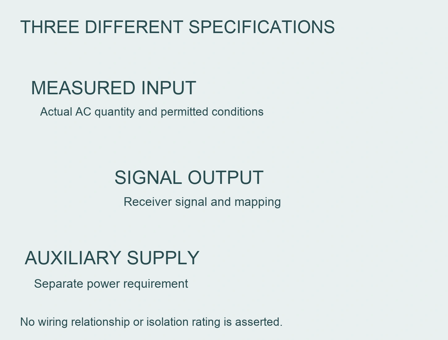
An AC input range describes the quantity presented to the measurement function. An analog output range describes the signal sent to a receiving device. The auxiliary supply powers the transducer. These are separate interfaces even when all three are expressed using electrical units.
For the RITOKS VDT-20 AC voltage transducer enquiry, request the selected measured range, output option, auxiliary supply and exact input application. The public page presents those options separately; it does not establish suitability for every line-to-line or line-to-neutral arrangement.
Do not read an output voltage option as permission to apply that voltage to the measured AC terminals. Do not read the auxiliary DC supply as the measured quantity. Keep the connection schedule and controller documentation aligned with the selected order configuration.
A selected RS485 interface does not establish the application protocol. Obtain the exact protocol and register documentation if a digital output is proposed. Do not call it Modbus without evidence for that configuration.
Define waveform and measurement behaviour
The phrase AC voltage does not by itself specify how a device responds to every waveform. Request the supported frequency, waveform conditions and measurement principle for the exact model. Do not presume true-RMS behaviour or suitability for an inverter output from a broad product name.
Phoenix Contact describes its MACX MCR-VAC example as measuring sinusoidal AC voltage and converting it to standard analog signals. Its documentation also identifies model-specific electrical isolation. These are examples of information to request, not capabilities that can be transferred to VDT-20. Phoenix Contact, AC and DC voltage transducers.
Fluke's three-phase power-quality discussion highlights correct system configuration and explains that an RMS reading alone does not describe waveform distortion. A single voltage signal should therefore not be advertised as a complete power-quality assessment. Its analyser functions and thresholds are not transducer specifications. Fluke, three-phase power-quality measurements.
Identify whether the monitoring purpose requires a steady voltage indication, event capture or a more complete waveform assessment. Response time, bandwidth and recording capability need their own evidence. The public VDT-20 page does not confirm all of those details, so they remain supplier questions rather than assumed features.
Check input limits beyond the span label
A measurement span is not the whole input-suitability specification. Ask for the applicable continuous input limits and documented overvoltage conditions, along with the input-to-earth and insulation information needed by the designer.
The Schneider example distinguishes permitted direct-connect conditions in its particular application context. Do not borrow its installation-category rating or voltage limits for another device. A manufacturer's statement for one model is not evidence for the next model on the procurement list.
Similarly, do not infer galvanic isolation from the fact that a transducer has separate input, output and supply terminals. Obtain the actual isolation description and applicable ratings. Phoenix's documented isolation is specific to its products, not proof of a universal transducer property.
If the requested application is outside the supported configuration or documentation is incomplete, resolve the measurement architecture with the designer and supplier. This guide does not approve an improvised adapter, protective connection or external transformer arrangement.
Make the controller tag describe the real input
The controller's engineering-unit tag should identify the measured pair and location, not simply say voltage. Retain the selected input span and output mapping with the channel record. That makes a future replacement less likely to inherit the wrong interpretation.
If a displayed quantity is calculated rather than directly measured, label it accordingly and document its assumptions. Do not transform one channel into an assumed measurement of every phase. Actual system configuration and operating conditions cannot be replaced by an unexplained software conversion.
A single-channel transducer reports its defined input quantity. It does not automatically establish all three phase voltages, phase sequence, voltage imbalance or neutral condition. Those objectives may require a different documented measurement arrangement.
Use this original interpretation checklist when reviewing the quotation and controls schedule.
| Description encountered | What to clarify | Conclusion not justified by the label alone |
|---|---|---|
| Two voltage terminals | Actual permitted node pair and diagram | Second terminal is always neutral |
| AC input span | Waveform, frequency and input application limits | Suitable for every AC source within the number |
| Analog output option | Signal mapping and receiving-channel requirements | Output volts are the measured-input allowance |
| Auxiliary DC supply | Separate supply terminals and requirements | Supply return is measurement neutral |
| RS485 | Exact application protocol and data map | Modbus support is proven |
| Single voltage channel | Actual measured pair and reporting scope | All-phase monitoring or imbalance detection |
| Separate interfaces | Documented insulation and isolation properties | Galvanic isolation is automatically present |
Release a configuration-specific record
Keep the accepted single-line reference, node definition, exact order code, supplier terminal diagram, input evidence and output mapping together. Record which document revision supports each unresolved-to-resolved decision.
For any planned verification, qualified personnel should use an authorised procedure suited to the selected equipment and installation. Do not use this article as permission to connect test leads in an energised panel, substitute earth for neutral or intentionally disturb the supply.
The acceptance record should compare the intended quantity with an appropriately defined reference and document the actual conditions. Do not manufacture test readings or a calibration claim from a supplier accuracy line. A valid controller display also does not independently prove that the input reference and insulation application are correct.
When replacing the transducer or moving the channel to another feeder, revisit the node pair and system definition. Reusing the old output scale may be convenient, but it does not establish that the new measured quantity has the same reference or permitted conditions.
Các câu hỏi thường gặp
Can a two-terminal voltage input measure either line-to-line or line-to-neutral?
Only where the exact device documentation permits the proposed application. Terminal count alone does not decide the reference, input-to-earth conditions or suitable system arrangement.
Can protective earth replace neutral for a voltage measurement?
Do not assume that substitution. Identify the actual measurement nodes and obtain the designer-approved configuration. Neutral, protective earth and controller common are not interchangeable labels.
Does an RS485 output mean the transducer supports Modbus?
No. Request the selected configuration's application protocol and data map. A physical interface description is not enough to identify the protocol or register meaning.
Can one transducer prove the three-phase supply is balanced?
Not automatically. A single channel represents its defined input pair. All-phase or imbalance assessment needs its own supported measurement scope and evidence.
Tài liệu tham khảo
- Schneider Electric. (n.d.). EasyLogic PM1125H/PM1110H direct-connect voltage limits, PHA5538902-05. Exact-meter configuration example only. Accessed October 2, 2026.
- Phoenix Contact. (n.d.). AC and DC voltage transducers. Exact-product waveform, signal and isolation examples only. Accessed October 2, 2026.
- Fluke. (n.d.). Moving up to three-phase power-quality measurements. Qualitative system-configuration and waveform distinctions. Accessed October 2, 2026.