
技術資源 · 技術解說
Modbus Energy Meter Selection: Protocol and Register Evidence
Modbus energy meter selection is more than finding “RS485” or “Modbus” on a product page. An integrator needs to know which physical interface and protocol variant the exact meter supports, how its measurements are represented in registers, and how the meter is configured for the connected circuit. Without that evidence, a device may respond to a network scan yet still deliver wrong or unusable energy values.

This guide focuses on the documentation required before a meter is committed to a BMS, SCADA or production-monitoring project. It does not assert protocol support for every RITOKS meter variant. Confirm the order code, firmware, register-map revision and electrical measurement setup for the exact unit.
Separate four integration layers
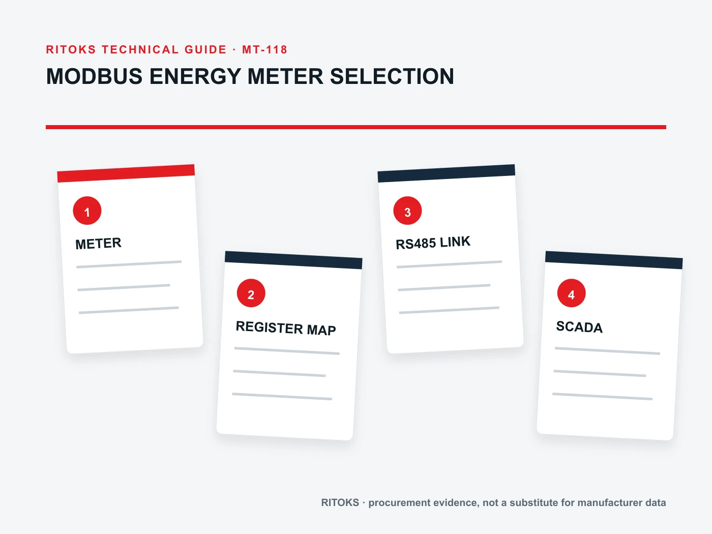
First is the measurement circuit: phase system, voltage connection and direct-input or CT-input architecture. Second is the communications hardware, such as an RS485 port or Ethernet interface. Third is the Modbus transport and application protocol. Fourth is the device-specific data model: addresses, values, scaling and status. A correct answer at one layer does not prove the next layer works.
The Modbus Organization publishes separate application-protocol, serial-line and TCP/IP guidance. The application protocol describes function codes used in transactions. This does not supply the register map for an individual energy meter. A project needs both the relevant protocol implementation details and the meter maker's current register document.
Record the integration target. A BMS may need live power and cumulative energy; a test bench may require demand, alarms or phase diagnostics. Asking for every available register creates unnecessary mapping work. Specify the required points, units, update frequency and acceptance method before comparing meters.
Verify the transport and network role
Ask whether the proposed order code exposes Modbus RTU over RS485, Modbus TCP over Ethernet, or another implementation. “Modbus compatible” is too broad for cabling and gateway design. Confirm connector or terminal layout, allowed network topology, termination and biasing guidance from the exact installation manual.
For a serial project, record address settings, supported baud rates, parity and stop-bit options. Confirm who sets them and how they survive power cycling. Different settings on one bus can make a correctly wired device look defective. Maintain a bus address schedule so replacement equipment can be commissioned consistently.
For a TCP project, confirm how network addressing, connection management and gateway behavior are configured. A separate RS485-to-TCP gateway can introduce its own address mapping and timing limits. Do not describe an RS485-only meter as native Modbus TCP because a gateway can be added elsewhere in the system.
Request the exact register map
A useful register document identifies each measurement by address, object type, supported function code, number of registers, data type, signedness, scaling, unit and access direction. It should say what a read returns when a measurement is unavailable or the meter is in an alarm state. Request the document revision linked to the firmware being supplied.
Address notation is a frequent trap. Some software presents one-based “4xxxx” labels while the transmitted protocol uses a zero-based address field. The mapping rule must be stated for the integration platform and checked with a known register. Copying a spreadsheet address without this interpretation can shift every point by one.
Confirm the byte and word order for multi-register values. A 32-bit integer or floating-point energy value may occupy two 16-bit registers, but its order and interpretation are device-specific. A plausible number is not proof of a correct decode; compare it with the meter display or a controlled reference condition.
Check whether cumulative energy is returned as a scaled integer, floating-point value, or multiple registers with a factor. Record how rollovers, import/export direction and reset behavior are represented. Historical trend errors often arise from misunderstood scaling or counter width, not from a broken serial connection.
Do not separate data mapping from meter setup
Input wiring and CT configuration determine what the register values mean. A meter connected through current transformers may require primary and secondary settings, phase association and polarity checks. A direct-input model has different circuit constraints. If these are wrong, Modbus can reliably transmit an inaccurate electrical result.
Document the phase system and wiring diagram used during commissioning. Compare phase voltage, current and power direction with independent expectations. A swapped CT or voltage phase can produce a convincing total that fails under load changes. Communication validation and metrology validation are related but separate tests.
Where the project requires billing or compliance use, check the applicable accuracy and certification evidence independently. The existence of a register labeled “energy” does not establish a meter's accuracy class, calibration status or legal suitability. Keep communication claims and measurement claims traceable to separate documents.
Plan realistic polling and exception handling
Define how often the system needs each point. Fast electrical telemetry, periodic energy totals and static identification registers need not share one poll interval. On a multi-device serial bus, excessive requests or long timeouts can delay the whole sequence. Test the planned point list and schedule with the actual gateway and number of meters.
Document how the integration handles no response, illegal address, illegal function and stale data. The Modbus application specification defines protocol behavior, but the BMS must decide how to display or alarm on a missing measurement. A trend value should not silently remain “healthy” after communication has failed.
Keep write operations under deliberate control. If the meter exposes configuration registers, distinguish them from read-only measurements and restrict the commissioning procedure to authorized settings. An integration that needs only monitoring should not assume it must write anything to the device after setup.
A small acceptance test that catches large mistakes
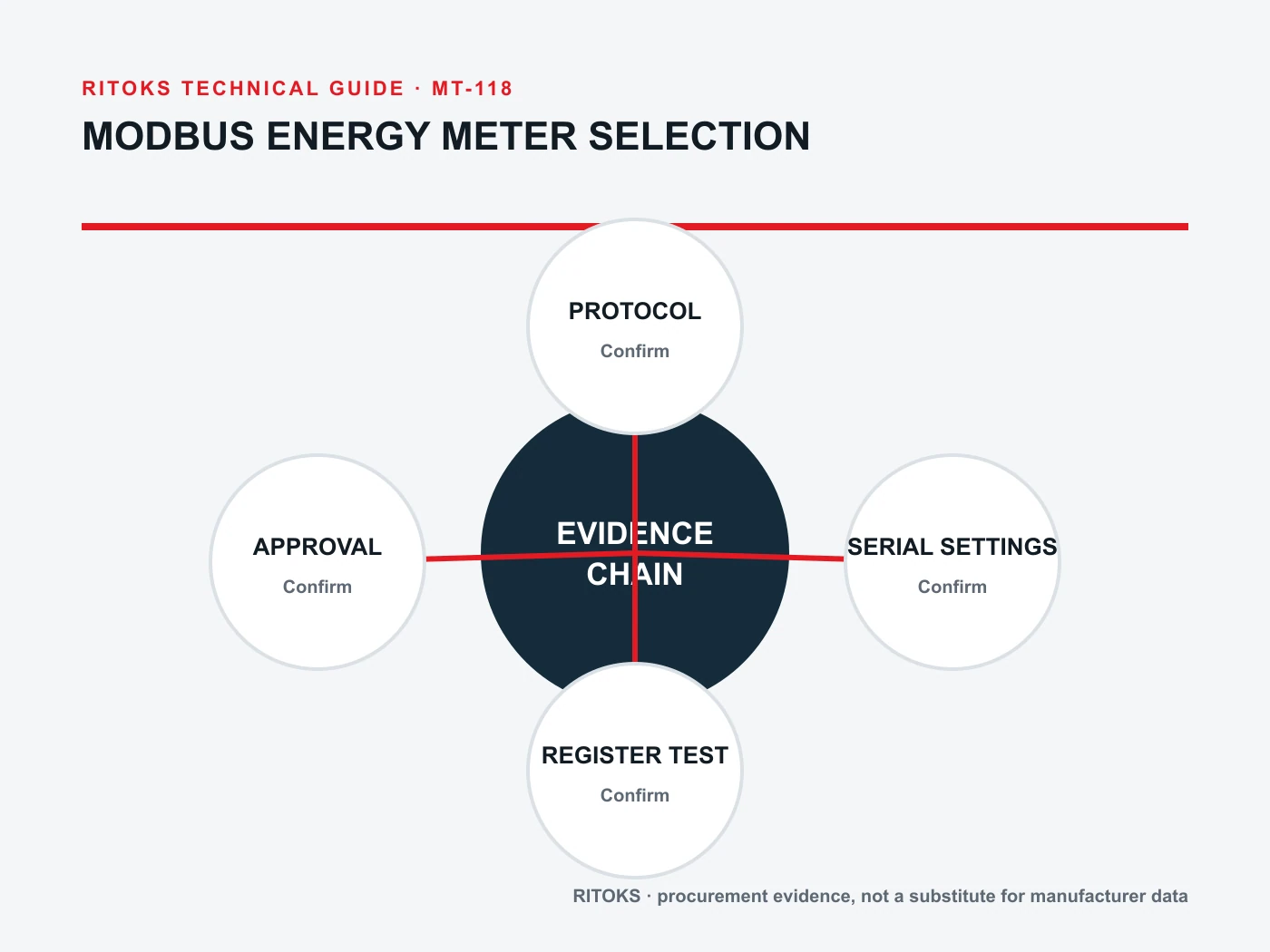
| 檢查 | Evidence to record | Typical failure revealed |
|---|---|---|
| Identity | Order code, firmware, map revision | Wrong variant or map |
| Transport | Settings and successful raw request | Bus or gateway mismatch |
| One live value | Address, type, scale, display comparison | Offset or byte-order error |
| Energy total | Initial and later reading under known load | Counter or unit misread |
| Loss of communication | Timeout and stale-data behavior | False healthy status |
Record the raw response alongside the interpreted value for at least one value of each data type. A signed-off example makes future software upgrades and meter replacement much safer. Retest after firmware or gateway changes because register interpretation or timing may change even when the wiring does not.
For sourcing, review the RITOKS DIN-rail energy-meter category and the specifically named RS485 Modbus meter page. 該 DDS1108 以及 DTS5158B pages illustrate other meter families, but their communications capability must be confirmed by variant; this guide does not imply they all support Modbus.
Send the desired phase system, circuit diagram, required point list, transport, integration software and expected quantities to RITOKS. Request the exact model's manual, register map, settings procedure and a sample read for a representative value before finalizing the control-system database.
Build a data-point schedule before buying
List each requested point in plain engineering language: total active energy, phase current, line voltage, active power, power factor or another named measurement. For each, state the desired engineering unit, the update interval and whether the value is needed for display, alarming, reporting or control. A generic request for “all Modbus points” does not show whether the candidate meter can satisfy the project's actual information need.
Mark which points are mandatory and which are optional. A candidate may expose sufficient electrical data but not a specific diagnostic status. This distinction lets the integrator compare an exact register map without rejecting a useful meter for an unnecessary feature or accepting one that lacks a critical measurement.
Assign ownership for configuration changes. If an electrician changes the CT ratio at the front panel while software keeps an external scaling factor, the reported value can be multiplied twice. Prefer one documented source of truth and record the as-left meter settings in the commissioning file. A later replacement should restore those settings before the trend is trusted.
Preserve evidence across revisions
Register maps sometimes differ between firmware or communication-module revisions. Keep the exact PDF or data sheet issued for the purchased unit with the automation project, not merely a link to a current generic download. Capture model, communication option and firmware identification from the meter during acceptance so future maintainers can match the installed population to its documentation.
When the site changes BMS software or gateway hardware, rerun a small set of known-value checks before migrating all points. Address-base interpretation, word order and timeout behavior can change at the integration layer without any physical meter change. The signed-off raw-response examples provide a baseline that isolates software mapping mistakes from electrical measurement issues.
Distinguish unsupported readings from a genuine zero. A stopped machine can legitimately draw little current, whereas a missing response or unavailable register is an integration fault. Design the dashboard and alarms so those states are not silently collapsed into the same number. This matters when energy data feeds operational decisions or maintenance reports.
常見問題
Does “RS485” guarantee Modbus RTU?
No. RS485 describes an electrical interface. Confirm the protocol and its serial settings for the exact order code.
Is a register list enough for integration?
Only if it includes address interpretation, function, length, type, word order, scale and units, and matches the supplied firmware. Validate representative reads on hardware.
Why can a meter communicate but still show the wrong energy?
Possible causes include wrong CT setup, wiring, phase association, register offset, scale or data order. Compare the electrical installation and raw data before changing a dashboard formula.
總而言之
Choose a Modbus energy meter only when the exact unit can be tied to a documented transport, configuration method and register map, then verified on the intended system. A successful ping or readable value is the beginning of commissioning, not its completion.
參考文獻
- Modbus Organization, specifications and implementation guides.
- Schneider Electric, iEM3400/iEM3500 meter user manual (illustrative of device-specific configuration; not a RITOKS specification).