
AC Surge Protective Devices for Low-Voltage Systems · Technical Explainer
SPD Lead Length and Routing: Reviewing the Installed Protection Level

Quick answer
An SPD's declared voltage protection level, Up, is a device characteristic. Its connecting conductors can add a voltage contribution during a surge, so equipment does not necessarily see the catalogue Up alone. Assess the actual routed protection path—including an external fuse detour where the approved circuit has one—and its geometry, then compare the assessed installed result with the equipment's withstand requirement. Straight-line cabinet distance and larger copper alone do not answer that question.
A quotation can contain the correct SPD and still leave the board layout unresolved. The device sheet states one protection characteristic; the assembly drawing places the device between connection points that may be far apart. Purchasing needs both records before treating the offer as an accepted installed protection arrangement.
Use the route-audit method below to ask for evidence, not to redesign a live board. Measurement, layout changes and final installation approval belong to qualified professionals working with the exact product and applicable requirements. The worksheet contains no universal conductor size, fuse rating or guaranteed voltage at a load.
Separate device Up from the installation result
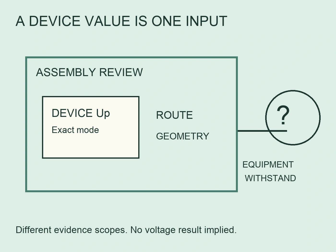
Schneider Electric explains that Up is defined and tested independently of the installation. Its guide distinguishes intrinsic protection from installed performance and compares the latter with equipment impulse withstand. That distinction prevents a catalogue value from becoming an unsupported promise about the complete cabinet or a remote load. Schneider Electric, SPD characteristics.
Keep two evidence sets. The first identifies the exact SPD variant, protected conductor pair and declared Up under the stated test conditions. The second identifies the protected equipment, the relevant withstand requirement and the approved installation arrangement. Do not fill gaps in the second set by repeating a number from the first.
For example, a buyer may know that the selected device has published mode-specific values but lack the equipment's rated impulse withstand documentation. The honest status is "equipment protection objective not yet confirmed." There is no reason to invent a pass threshold from the equipment's appearance or its ordinary operating voltage.
The same discipline applies when reviewing several devices in one assembly. Ask which equipment and protection mode each assessment covers. A value associated with one branch should not silently become the result for every phase-neutral and phase-earth relationship in the board. Record the scope next to the result, not in a separate email that can be lost.
Trace the routed path, not the cabinet distance
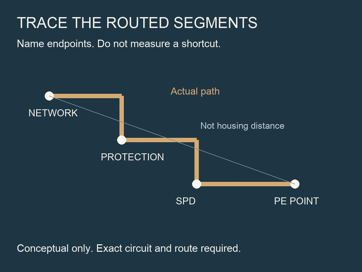
Schneider's connection guidance includes voltage contributions from connecting conductors in the installed result. Its cabling guidance includes the network-to-SPD route through external short-circuit protection and the route to the earthing terminal. The audit therefore needs named endpoints and the actual conductor route, rather than a ruler measurement between device housings. Schneider Electric, SPD connection; Schneider Electric, cabling rules.
Begin with a controlled assembly drawing. Identify the connection point on the active conductor, any intervening external protective device, the SPD terminals and the relevant protective-conductor termination. The responsible designer should identify which segments belong to the particular protection path being assessed. Different circuits should not be reduced to one unexplained length.
Next, mark every turn and detour on the as-built route record. A conductor may leave a terminal, run along a duct, pass a fuse holder and return to the SPD. The separation visible in a cabinet photo will not describe that complete route. Where access or operating conditions prevent a safe measurement, use a confirmed drawing and mark field measurement as outstanding.
| Route record field | Information to obtain | How to keep the record usable |
|---|---|---|
| Assessed mode and endpoint pair | Designer's named conductors and termination points | Assign a path identifier on the drawing |
| Network connection to external protection | Actual routed length, if that device is present | Record the duct route and drawing revision |
| External protection to SPD | Actual routed length and terminal identification | Keep separate from the preceding segment |
| SPD to approved protective termination | Actual routed path and destination | Identify the termination, not just "earth" |
| Geometry and construction | Conductor form, spacing, loop arrangement and assembly details | Attach an annotated drawing or controlled photograph |
| Equipment location and withstand evidence | Protected item, applicable mode and supporting document | Link the route record to the protection objective |
Use this table to structure a route record. Mark a segment "not present in this approved circuit" when appropriate; do not create a fictitious external fuse simply to fill a row. Keep the designer's approved criterion alongside the completed record.
Worked route record: find the omitted detour
Consider a hypothetical drawing review in which an approved circuit already includes an external protective device. The recorded route has three segments: 0.18 m from the named network connection to that device, 0.22 m from it to the SPD, and 0.16 m from the SPD to the identified protective termination. These are invented teaching dimensions, not a recommended arrangement, measured installation or permissible length limit.
| Route identifier | Hypothetical routed length | Why it belongs in this particular record |
|---|---|---|
| A: network connection to external protection | 0.18 m | The approved drawing includes this segment before the external device. |
| B: external protection to SPD | 0.22 m | It is a separate route, not a zero-length transition through the fuse holder. |
| C: SPD to identified protective termination | 0.16 m | It completes the selected connection-path record. |
| A + B + C | 0.56 m | This is the route inventory total, not a transient-voltage calculation or approval. |
A quotation photograph might show only 0.20 m of apparent spacing between the SPD and a nearby termination. That dimension and the 0.56 m route total answer different questions. The arithmetic 0.18 + 0.22 + 0.16 = 0.56 m exposes the omitted path; it does not establish which circuit is permitted, a voltage at the equipment or compliance with a particular instruction.
Suppose the layout is revised and segment B becomes 0.34 m because it must go around a duct. The recorded total then becomes 0.68 m: 0.18 + 0.34 + 0.16. The change is 0.12 m, even if the visible spacing between housings remains 0.20 m. Return that changed route to the designer instead of attaching the old acceptance to a new drawing. No universal voltage-per-metre figure is needed to detect the discrepancy.
This example makes the buying decision more precise. The missing item is not necessarily a different SPD; it may be an accurate route record for the already proposed circuit. Once the route is correctly described, the qualified reviewer can apply the exact manufacturer instructions and assessment method. If the design uses a different connection arrangement or no external device, the relevant segment inventory must change rather than inheriting these three rows by habit.
Keep the outward equipment circuit as a separate recorded relationship. Its location and withstand evidence are needed for the wider protection assessment, but adding its distance to this example by default would silently change what the total represents. A useful calculation has named endpoints, a defined scope and units; otherwise even correct arithmetic can answer the wrong question.
Include backup-fuse detours in the layout review
Phoenix Contact's main-distribution guidance explains that partial voltage contributions along the complete connection must be considered with device protection. It specifically includes routes to and from a backup fuse. A review that measures only the lead attached directly to the SPD can therefore omit part of the arrangement under assessment. Phoenix Contact, main power distributions.
Check the offer's protection scope before marking the physical route. Is external protection required for the proposed combination, included in the supply, or already present in the board? The answer must come from exact coordination information and project data. An external holder shown in a catalogue illustration is not evidence that it belongs in every installation.
If the approved circuit includes an external fuse, ask the layout reviewer to include the connecting detour in the assessment. Do not treat the holder as a zero-length transition between arbitrary points. Keep the electrical coordination question and the physical route question connected, while preserving their different evidence requirements.
Some manufacturer products integrate protection, but a generic integrated-fuse claim should not be transferred to an unrelated SPD. Likewise, removing an external protective device to shorten a route is not a procurement shortcut. Any such change needs a new model-specific coordination and assembly review, not just a cleaner drawing.
Review geometry without assuming metal is a perfect return path
Conductor length is one part of the review. Phoenix Contact discusses geometry-dependent voltage contributions and warns that mounting-plate paths also need assessment. Schneider's connection example permits enclosure use as a protective path only where the assembly manufacturer confirms suitable construction. Neither source treats an arbitrary metal cabinet as a zero-impedance conductor. Phoenix Contact, main power distributions; Schneider Electric, SPD connection.
For procurement, request an annotated route rather than a statement that the cabinet is "all metal." If a designer's proposed assessment includes a mounting plate or another assembly part, identify the relevant connections and obtain the assembly evidence. A painted surface or a familiar enclosure outline does not establish an accepted protective path by itself.
The neatness of cable dressing answers a different question. Schneider's cabling discussion addresses loop area and separation of incoming conductors from protected outgoing conductors to limit coupling. A bundle can look orderly while the review still lacks evidence about those relationships. Schneider Electric, cabling rules.
Ask the designer to show these relationships on the layout revision. Do not convert a conceptual review image into instructions to relocate conductors in an energized assembly. If available cabinet space limits the proposed route, record the constraint so the designer can assess a supported alternative. Concealing the constraint behind a short idealized line makes the RFQ less useful.
Do not convert lead length into a universal voltage figure
Schneider's connection guidance uses an illustrative impulse calculation to explain inductive connection effects. That calculation has specified waveform and current assumptions. An installer cannot take a remembered voltage-per-metre figure and apply it to every route, SPD or assembly. The review needs the stated conditions and the designer's selected method. Schneider Electric, SPD connection.
The underlying relationship links inductance and current rate of change. Length alone does not supply those inputs. If a supplier presents a calculated installed voltage, ask for the assessed mode, connection geometry, current assumptions and treatment of each segment. A result with units but no calculation scope is not a completed assessment.
Avoid a second shortcut: specifying thicker copper as the entire remedy. Schneider distinguishes high-frequency connection effects from conductor-duty considerations. The route review and the conductor's required current or fault withstand checks should both be documented; improving one property does not prove that the whole arrangement is accepted. Schneider Electric, SPD connection.
The purpose of the audit is to locate missing evidence, not to replace an engineer with a spreadsheet. Where the selected instruction states connection constraints, retain their scope and ask the designer to resolve a proposed departure. Do not turn an educational rule from one national context into a universal compliance certificate for another project.
Request an assembly-level handoff
An SPD route handoff should connect the final drawing, actual connection record and equipment protection objective. Ask the responsible reviewer to identify the accepted arrangement and any unresolved item. An approved device list alone does not record whether fuse detours, construction details and the protected equipment were included in the installation assessment.
| Handoff item | Evidence needed for the purchasing record | Unresolved condition to flag |
|---|---|---|
| Selected SPD | Exact variant and mode-specific technical sheet | Family title without an orderable configuration |
| Final connection arrangement | Controlled circuit and layout revisions | Catalogue drawing differs from the proposed board |
| Route assessment | Named endpoints, segment record and assessment basis | Straight-line distance replaces actual route |
| Protection objective | Equipment withstand document and defined scope | Load capability inferred from cabinet appearance |
| Coordination and supply scope | Required external protection and included accessories | Fuse omission or pairing is unsupported |
| Acceptance record | Qualified review, conditions and outstanding actions | A sales statement is used as installation approval |
For sourcing, the GSP10-C40N Type 2 family provides a starting point for requesting the exact configuration sheet and connection instructions. The BR-12.5M Type 1+2 page documents its own product scope. Neither page establishes the assessed voltage for a customer's unspecified route.
Where equipment protection calls for consideration of an additional stage, the BR-T3 DIN-rail Type 3 family is a separate candidate for review. Do not assume that adding it repairs every upstream layout problem or that these product families form a verified coordinated combination. Obtain the required coordination evidence before presenting a combined offer as accepted.
Order against the reviewed arrangement
Keep the product sheet, connection route and equipment protection objective together in the purchasing file. Close the offer against the accepted drawing revision, not a cabinet photograph or an isolated Up value. If the arrangement changes during assembly, return the changed route to the responsible reviewer before claiming the original assessment still applies.
參考文獻
- Schneider Electric. (n.d.). Connection of Surge Protection Device. Electrical Installation Guide. Retrieved October 2, 2026.
- Schneider Electric. (n.d.). Cabling rules of Surge Protection Device. Electrical Installation Guide. Retrieved October 2, 2026.
- Schneider Electric. (n.d.). Common characteristics of SPDs according to the installation characteristics. Electrical Installation Guide. Retrieved October 2, 2026.
- Phoenix Contact. (n.d.). Surge protection in main power distributions. Retrieved October 2, 2026. Numerical manufacturer examples are not RITOKS installation results.