
Power Module Heatsinks · Technical Explainer
Heatsink Thermal Resistance: What the Rating Does and Does Not Prove
A heatsink thermal-resistance rating is a compact way to describe temperature rise for a defined heat flow and test condition. It is useful, but it does not by itself prove that a power semiconductor will remain within its temperature limit. The buyer still needs device loss, the complete thermal path, ambient conditions, airflow, orientation and mounting details.
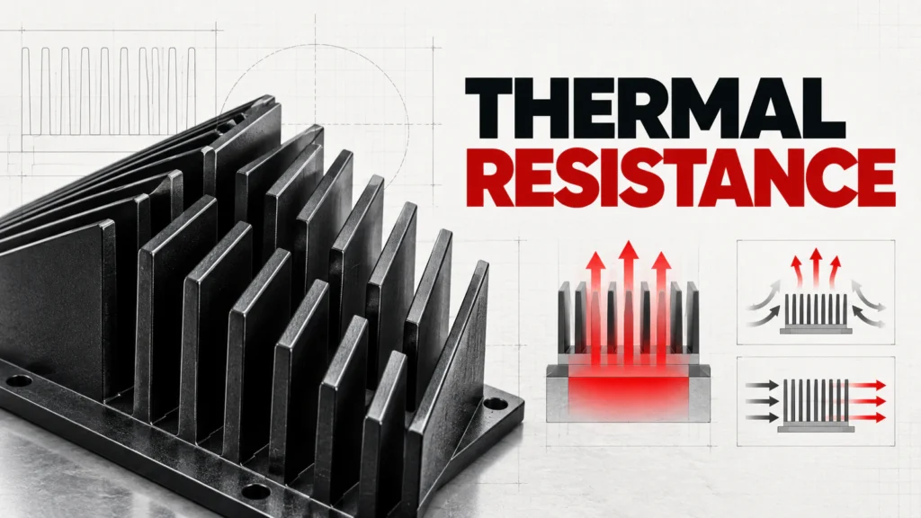
This article explains how to read a sink-to-ambient thermal-resistance value and where its authority stops. It does not calculate an approved heat sink for a particular SCR, diode or SSR, and it does not turn a family-level RITOKS page into exact-model thermal evidence.
Buying Decision at a Glance
| Decision input | Buyer must confirm | Evidence required |
|---|---|---|
| Thermal path | Which two reference points the rating connects | A clearly defined Rθ value and units |
| Heat input | Worst-case device dissipation under the real duty | Exact device loss curve or formula |
| Environment | Internal ambient, airflow, altitude and nearby heat sources | Test conditions and derating information |
| Assembly | Baseplate, interface material, flatness and mounting pressure | Exact installation instructions |
| Temperature limit | Permitted junction or case temperature with design margin | Exact semiconductor data |
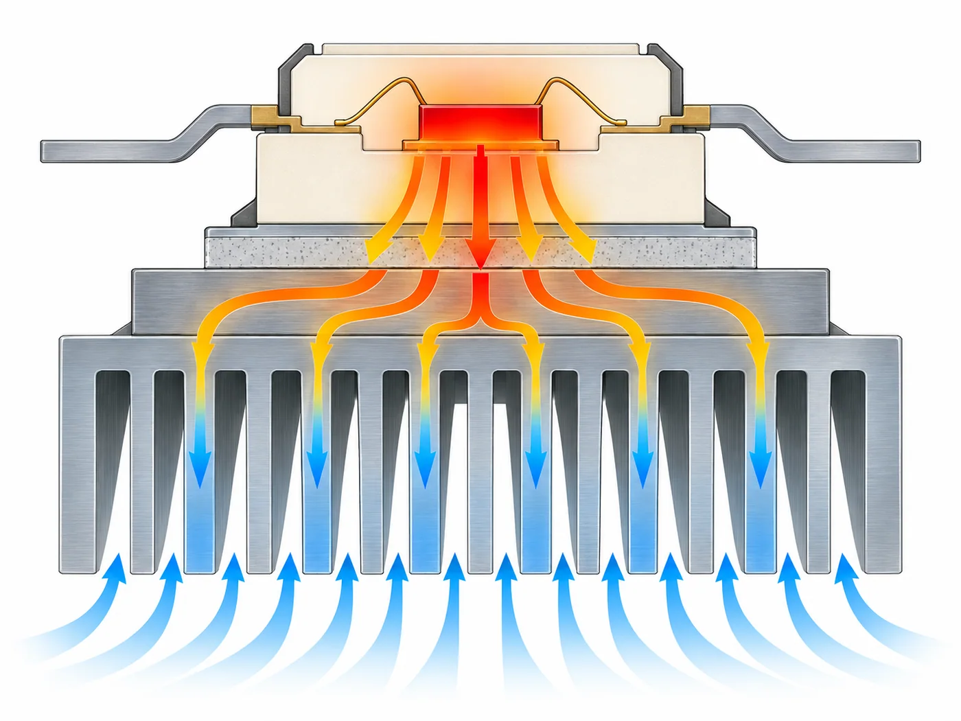
Start With the Meaning of Thermal Resistance
Thermal resistance expresses the temperature rise associated with each watt of heat crossing a defined path. A sink-to-ambient value therefore concerns the heat sink and its surrounding air; it is not automatically the junction-to-ambient value of the installed semiconductor assembly. Keep the two reference points with every number.
A lower value generally indicates less temperature rise per watt when the comparison uses the same definition and conditions. It is unsafe to compare two numbers when one is measured with forced air, one with natural convection, or when their orientation and temperature reference are different.
Build the Complete Temperature-Rise Chain
The full path can include junction-to-case resistance inside the semiconductor, case-to-sink resistance through the interface, and sink-to-ambient resistance. Multiply each applicable resistance by the heat flowing through that segment, then add the relevant temperature rises to the defined ambient reference.
Not every datasheet presents the path in the same way. Some assemblies integrate a baseplate or heat spreader; some publish case-temperature limits rather than a complete junction calculation. Follow the exact manufacturer method and never add terms that use incompatible reference points.
Read the Test Conditions Beside the Number
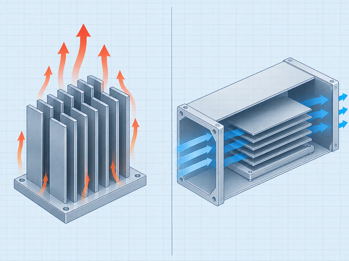
Heat-sink performance changes with orientation, fin spacing, air velocity, surface finish and the way heat enters the base. Natural-convection ratings are particularly sensitive to whether the fin channels allow warm air to rise freely. A number without its test conditions is incomplete purchasing evidence.
Forced-air data must identify airflow or air velocity and the measurement method. A fan nameplate airflow measured without restriction does not prove the same flow through a loaded enclosure, duct or fin field. Pressure loss and recirculation can reduce the cooling actually available.
Include the Thermal Interface
The contact between semiconductor base and heat sink is not perfect. Surface flatness, roughness, contamination, insulating pads, grease and mounting force affect the case-to-sink temperature rise. The interface must be designed and assembled according to the exact device and material instructions.
Do not assume that adding more compound always improves heat transfer. Excess material can increase bond-line thickness, and an electrically insulating pad can add thermal resistance. Record the chosen interface as part of the bill of material rather than treating it as an installer preference.
Separate Rating From Proof
A published sink rating is one input to a thermal design. Proof requires a traceable calculation using exact device loss and limits, followed by the verification required for the real assembly. The measured point, load, ambient and stabilization time should be recorded.
The result applies to the tested configuration. Changing enclosure ventilation, device spacing, mounting orientation or semiconductor type can reopen the calculation. A photograph of a large extrusion is never equivalent to a documented thermal path.
Build an Evidence File Before Approval
Create one review sheet for the proposed Power Module Heatsink order code. Put project inputs in one column and supplier evidence in the other. Preserve the exact pages, drawings, curves and tables used in the decision, including their revision or retrieval date. A category page can establish product-family context, but an exact rating or connection claim must trace to the quoted configuration.
Check that every accepted value describes the same orderable item. For a heatsink quotation, match the drawing, mounting footprint, airflow conditions and thermal-resistance evidence to the same quoted configuration. Do not combine a family maximum from one variant, a drawing from another and an optional feature from a third. Mark unresolved fields explicitly instead of allowing them to disappear in the commercial quotation.
Control Changes During Sourcing
Keep the application record frozen while suppliers respond. If the load, voltage, environment, duty, enclosure, cooling method or required output changes, issue a revised record and ask each supplier to reconfirm the candidate. Otherwise two quotations may look comparable while answering different technical requirements.
A proposed substitute returns to the same evidence gate. Matching dimensions, a similar product photograph or one equal headline rating is not enough. The substitute must satisfy the required functions and conditions with its own exact documentation.
Common Procurement Errors
- Selecting Power Module Heatsink from one headline rating while leaving the application context undefined.
- Using a curve, terminal diagram or performance claim from a neighboring model.
- Comparing free-air, nominal or family-maximum data with an application operating point.
- Treating included accessories and system functions as obvious from a product name.
- Approving a substitution without reopening the technical evidence review.
Do not compare sink-to-ambient thermal-resistance numbers measured with different airflow or fin orientations. Keep semiconductor loss, interface resistance and inlet ambient temperature in the same thermal review; extrusion length alone is not proof of performance.
How to Compare Supplier Offers
| Comparison point | Required evidence | Do not accept |
|---|---|---|
| Definition | Reference points and °C/W or K/W stated | Unlabeled “thermal performance” number |
| Convection | Natural or forced airflow conditions identified | Fan presence assumed to be sufficient |
| Heat source | Exact footprint and heat input condition | Any module on the same base |
| Mounting | Interface and pressure instructions available | Dry contact or arbitrary grease |
| Validation | Assembly temperature checked under defined duty | Touch temperature or brief no-load test |
Normalize every Power Module Heatsink offer to the same application record. Keep document revisions, test conditions and open questions beside each value. A proposal can remain commercially interesting while technically incomplete, but missing evidence must stay visible until it is resolved.
Decision Workflow
- Identify the exact semiconductor and its worst-case loss method.
- Define the maximum internal ambient and allowable device temperature.
- List every thermal-resistance segment with matching reference points.
- Select a heat sink under the intended orientation and airflow conditions.
- Specify the interface material and mounting method.
- Verify the assembled system at the defined load and environment.
Identify the exact semiconductor and its loss at the intended duty, then define permitted case or junction temperature and maximum sink-inlet ambient. Request heat-sink resistance under the intended convection or airflow conditions and check the interface separately.
RFQ Preparation Checklist
A useful RFQ for a power module heatsink is concise enough to answer and complete enough to prevent silent assumptions. Identify unknown values as questions and require an exact orderable code rather than a generic family recommendation.
- Exact semiconductor model and mounting footprint
- Worst-case power loss and duty cycle
- Required sink-to-ambient thermal resistance
- Natural or forced-air conditions
- Orientation, enclosure and internal ambient
- Interface material and mounting requirements
- Drawing, test conditions, quantity and destination
Request the current datasheet revision and the scope of any certification, compatibility or performance claim. Record quantity and destination after the technical inputs so commercial terms do not obscure unresolved engineering questions.
Stop Conditions Before Order Release
Do not release the order while a critical application input is unknown, the quoted model is ambiguous, a required rating is supported only by another manufacturer’s document, or installation conditions fall outside the available evidence. These are engineering gaps, not editorial details.
The approval record should state what the selected item does, what remains outside its scope and which exact documents support the decision. If the application or candidate changes, reopen the affected checks rather than carrying the previous conclusion forward.
Frequently Asked Questions
Does a 1 °C/W heat sink keep every device 1 °C above ambient?
No. The temperature rise depends on heat flow, the defined thermal path and all additional resistances in the assembly.
Can I compare °C/W and K/W directly?
For temperature differences their numerical size is equivalent, but the path and test conditions still must match.
Does a larger heat sink always have a lower rating?
Not necessarily. Geometry, fin efficiency, airflow, orientation and heat spreading all influence performance.
Related RITOKS Products and Guidance
Use these links as separate category and product records. A contextual link does not claim interchangeability, compatibility or an approved system combination.
Power Module Heatsink product category
Aluminum power module heatsinks
SF forced-air heatsinks for power modules
SSR heat sink selection guide
Technical References
These primary manufacturer sources support only the general concepts identified below. Their product values, diagrams and approvals do not transfer to RITOKS products.
OMRON, Further Information of Solid-state Relays
Supports the definition of thermal resistance and the need to match heat-sink performance, mounting and load conditions. OMRON model values do not transfer to RITOKS heat sinks.
OMRON, Solid-state Relay Safety Precautions
Supports attention to mounting surfaces, thermal interfaces and surrounding conditions. It does not approve a RITOKS assembly.
Request an Exact-Model Review
Send the application requirements, exact documentation questions, quantity and destination through the RITOKS contact form. An RFQ requests an exact-model review; this guide does not approve a wiring design, installation or automatic substitute.