
Digital Panel Meters · Technical Explainer
RS485 Modbus Panel Meters: Data and Integration Evidence
An RS485 Modbus panel meter combines at least three selection layers: the electrical measurement function, an RS485 physical link and a documented Modbus implementation. A terminal marked RS485 does not prove Modbus support, and a Modbus label does not prove the register map, measured quantities or scaling required by the control system.

This explainer defines the integration evidence buyers should request. It does not publish a RITOKS register map, prescribe network wiring or claim that every RITOKS panel meter supports the same protocol, baud rate, address range, supply or measurement inputs.
Buying Decision at a Glance
| Decision input | Buyer must confirm | Evidence required |
|---|---|---|
| Measurement | Quantities, direct or transformer input, range and accuracy | Exact meter datasheet |
| Serial layer | RS485 terminals, baud, parity, stop bits and address | Exact communications manual |
| Protocol | Modbus RTU or another implementation and device role | Protocol declaration |
| Data model | Register addresses, type, length, order and scaling | Versioned register map |
| Commissioning | Polling, timeout, exceptions and test values | Integration test record |
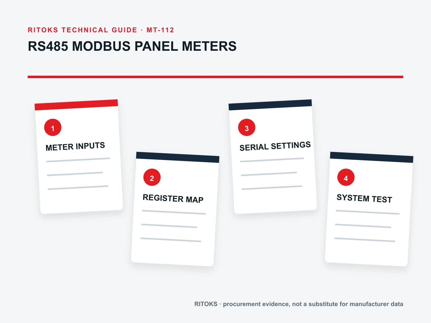
Separate RS485 From Modbus
RS485 describes an electrical signaling layer used for serial communication. Modbus defines messages and data access above that link. Equipment can use RS485 with a proprietary protocol, so the two terms should never be treated as synonyms in an RFQ.
Ask the supplier to state the supported Modbus mode and device role. For a serial network, record baud rate, parity, stop bits, address-setting method and supported address range from the exact manual. Do not copy settings from a similar front panel.
Define the Measurement Chain First
Specify what the meter must measure and how signals reach it. Record system phase arrangement, nominal values, direct or transformer inputs, CT or PT ratios, auxiliary supply and required measurement outputs. Communications cannot correct an incompatible electrical input.
Accuracy statements must remain tied to the exact quantity, range, reference condition and model. If current transformers are used, their ratio, polarity, burden and class form part of the measurement chain. The panel meter and sensor documents should be reviewed together without claiming automatic compatibility.
Request a Versioned Register Map
The register map should identify address, function, access, data type, length, byte or word order, units, scale factor and availability by model or firmware. A single screenshot from commissioning software is not a durable integration document.
Keep raw-register representation separate from engineering units. A signed integer, unsigned integer and floating-point value can occupy similar-looking addresses but require different interpretation. The integrator should not infer data type from a plausible displayed number.
Plan the Serial Network Boundary
Document topology, cable type, reference conductor, shielding approach, termination and biasing according to the exact equipment and network design. RS485 is commonly arranged as a bus rather than an uncontrolled star, but the responsible engineer must follow the device instructions and site rules.
List every device address and prevent duplicates before commissioning. Cable length, device count, baud rate, grounding environment and isolation can affect reliability. This article does not set universal limits because the valid boundary depends on transceivers, cable and installation.
Commission With Known Electrical Values
Test communication before integrating dashboards or alarms. Confirm one meter at a time with known address and serial settings, then read documented identification or measurement registers. Compare reported engineering values with the local display and an appropriate reference.
Record timeout, retry and exception handling in the master system. Preserve the meter model, firmware, register-map revision and configuration export. If firmware or model changes, recheck the map instead of assuming address compatibility.
Build an Exact-Configuration Evidence File
Create one review sheet for the proposed Panel Meter order code. Put project inputs in one column and supplier evidence in the other. Preserve the exact datasheets, drawings, curves, tables and manuals used in the decision, including their revision or retrieval date. A category page can establish family context, but an exact rating, setting, protocol or connection claim must trace to the quoted configuration.
Check that every accepted value describes the same orderable item. Similar housings and family names can hide different circuits, supplies, terminals, controls, mounting details or accessories. Do not combine a family maximum from one variant, a drawing from another and an optional feature from a third. Keep unresolved fields visible in the technical comparison.
Control Changes During Sourcing
Freeze the application record while suppliers respond. If the load, voltage, environment, duty, enclosure, control method or required output changes, issue a revised record and ask each supplier to reconfirm the candidate. Otherwise quotations can appear comparable while answering different technical requirements.
A proposed substitute returns to the same evidence gate. Matching dimensions, a similar product photograph or one equal headline rating is not enough. The substitute must satisfy the required functions and conditions using its own exact documentation.
Common Procurement Errors
- Selecting a Panel Meter from one headline value while leaving the application context undefined.
- Using a curve, setting table, register map or connection diagram from a neighboring model.
- Treating a family maximum or ideal test condition as the application operating point.
- Assuming included accessories, controls and system functions from the product name or photograph.
- Approving a substitution without reopening the technical evidence review.
A terminal marked RS485 does not establish a usable Modbus register map. An integration offer needs the exact meter's electrical inputs, serial settings, protocol mode and versioned register documentation; a screenshot from another model is not a substitute.
How to Compare Supplier Offers
| Comparison point | Required evidence | Do not accept |
|---|---|---|
| Evidence item | What it must answer | Insufficient substitute |
| Electrical datasheet | Input, supply and measurement functions | RS485 logo |
| Serial settings | Baud, parity, stop bits and address method | “Modbus compatible” |
| Register map | Address, type, scaling and access | Unversioned spreadsheet fragment |
| Network plan | Topology, cable and termination responsibilities | Terminal names alone |
| Test record | Known values, errors and configuration | One successful software screenshot |
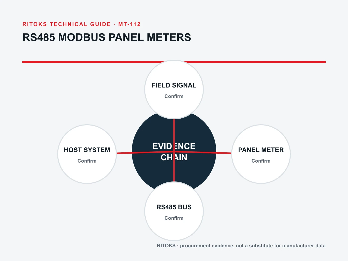
Normalize every Panel Meter offer to the same application record. Keep document revisions, test conditions and open questions beside each value. A proposal can remain commercially interesting while technically incomplete, but missing evidence should stay visible until resolved.
Decision Workflow
- Define measured quantities and electrical input architecture.
- Select an exact meter with documented RS485 Modbus support.
- Obtain the current communications manual and register map.
- Freeze serial settings, addresses and network plan.
- Configure ratios and scaling from exact documents.
- Commission with known values and archive the final configuration.
Define the measurement chain before the network: phase arrangement, direct or transformer inputs, auxiliary supply and required quantities. Then check the exact meter's Modbus mode, serial settings and register scaling against the intended controller.
RFQ Preparation Checklist
A useful RFQ for panel meter rs485 modbus is concise enough to answer and complete enough to prevent silent assumptions. Identify unknown values as questions and require an exact orderable code rather than a generic family recommendation.
- Measured quantities and phase arrangement
- Direct, CT or PT input requirements and ratios
- Auxiliary supply and output requirements
- RS485 electrical and isolation information
- Modbus mode, serial settings and address method
- Versioned register map with data types and scaling
- Firmware, manuals, quantity and destination
Request the current datasheet and manual revisions and the scope of any certification, compatibility or performance claim. Record quantity and destination after the technical inputs so commercial terms do not obscure unresolved engineering questions.
Stop Conditions Before Order Release
Do not release the order while a critical application input is unknown, the quoted model is ambiguous, a required claim is supported only by another product document, or installation conditions fall outside the available evidence. These are engineering gaps, not editorial details.
The approval record should state what the selected item does, what remains outside its scope and which exact documents support the decision. If the application or candidate changes, reopen the affected checks rather than carrying the previous conclusion forward.
Frequently Asked Questions
Does an RS485 port guarantee Modbus support?
No. RS485 is a physical layer. The exact protocol and implementation must be documented.
Can two meters use the same Modbus address?
Not on the same master segment when the master must distinguish them. Assign and record unique addresses.
Why is the register-map revision important?
Models and firmware can differ in address, type or feature availability. The integration record must match the exact meter.
Related RITOKS Products and Guidance
Use these destinations as separate category, product and guidance records. A contextual link does not claim interchangeability, coordination, compatibility or approval for a particular application.
D85 AC digital voltage and current panel meter
Multifunction digital power meter with RS485
AD16-22 LED digital voltage panel meter
Single-function vs multifunction panel meters
Technical References
These primary standards or manufacturer sources support only the general concepts identified below. Their product values, diagrams, approvals and tested combinations do not transfer to RITOKS products.
Modbus Organization, MODBUS over Serial Line Specification and Implementation Guide
Supports the separation of the Modbus application protocol from serial-line framing, addressing and physical implementation. The document does not prove any exact RITOKS register map or serial settings.
Schneider Electric, PowerLogic Multifunction Power Meters
Supports distinguishing measured quantities, input architecture and communications functions. Schneider meter functions and protocols do not describe RITOKS meters.
Request an Exact-Model Review
Send the application requirements, exact documentation questions, quantity and destination through the RITOKS contact form. An RFQ requests an exact-model review; this guide does not approve a wiring design, protection setting, installation or automatic substitute.