
Motor Starters for Industrial Motor Control · Technical Explainer
Magnetic Motor Starter Components: Functional Relationship Guide
A magnetic motor starter is an assembly with separate jobs to perform. The contactor switches the motor circuit under control, an overload function responds to sustained motor overload, and a short-circuit protective device handles fault duty. An enclosure, controls and accessories may also be part of the delivered starter. Treating all of these as one undifferentiated box makes selection and replacement difficult.
This guide explains the functional relationship among those components. It is not a wiring diagram for a particular panel or a claim that any two product families have been coordination-tested together. Exact motor and device documents determine the final assembly.
The contactor performs controlled switching
The contactor is the device that opens and closes the motor power path when its coil control circuit commands it. It may be started and stopped by a pushbutton, controller, interlock or other approved control element. Its selection depends on motor voltage, current, starting method, duty and the utilization category relevant to the application.
Do not choose a contactor from a generic ampere number alone. Motor starting and stopping can stress contacts differently from a resistive load. The exact contactor datasheet should identify the duty assumptions, coil supply options and accessory compatibility. A control-voltage mismatch can make an otherwise plausible power contactor unusable in the panel.
The contactor does not by itself provide complete motor overload or short-circuit protection. It is a switching component in a coordinated circuit. Schneider Electric's motor-starter catalog presents combinations of contactor, overload relay and short-circuit protective devices, illustrating why assembly-level review matters.
The overload function responds to sustained motor stress
Overload protection monitors the motor current or another relevant condition and initiates a trip when the motor is exposed to excessive load for too long. It is not the same job as interrupting a high-energy short circuit. An overload relay may open the contactor control circuit, causing the contactor to drop out. The actual arrangement must be checked in the selected starter schematic.
Motor nameplate current, starting behavior, ambient conditions, trip class and reset policy influence overload selection. A higher setting is not automatically safer from nuisance trips; it can leave the motor underprotected. A lower setting can interrupt normal starting. The engineer should compare the motor duty and relay characteristic rather than assuming a default.
Some starter architectures incorporate the overload function in an MPCB or another protective device rather than a separate relay. The functions still need to be identified in the circuit documentation. A buyer should ask which component performs overload protection and how its setting is established.
Short-circuit protection is a separate decision
Fault current can exceed the normal motor-starting current by a large margin. A fuse, circuit breaker or another approved short-circuit protective device is selected for the system fault level and its relationship with downstream starter components. The exact combination can affect the permitted short-circuit performance of the starter assembly.
Do not infer short-circuit rating from the contactor size or motor power. Consult the manufacturer's coordination tables and the applicable panel-design standard for the combination actually installed. A component replacement with similar dimensions may change the assembly coordination evidence.
IEC 60947-4-1 addresses electromechanical contactors and motor starters, including overload protection and related arrangements. The standard scope helps frame the discussion, but a catalogue reference to IEC does not establish the tested performance of an arbitrary RITOKS component combination. Ask for exact-model documentation where coordination is required.
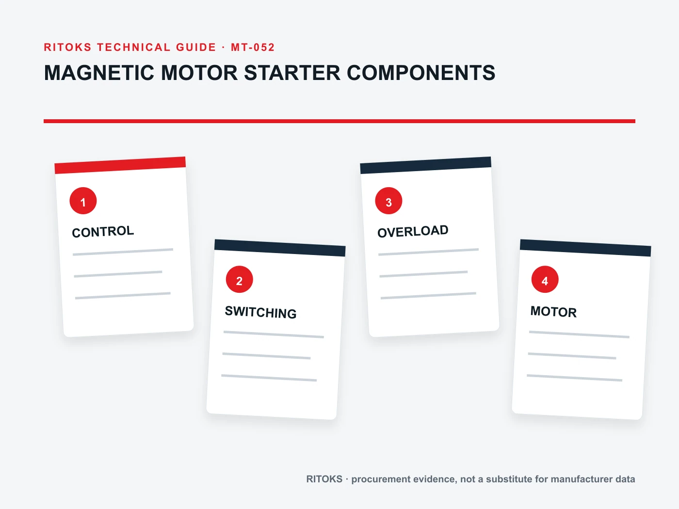
The enclosure and control circuit complete the assembly
An enclosed starter adds physical and environmental constraints. Cabinet dimensions, ingress protection, ambient temperature, ventilation, wiring space, cable entries and service access affect how the devices operate and are maintained. An enclosure protects components only when installed and sealed as intended; its label does not remove the need for heat and ingress assessment.
The control circuit may include start/stop pushbuttons, auxiliary contacts, interlocks, emergency-stop interfaces and status indication. Each feature must be identified in the schematic. The control supply, coil voltage and the desired response to supply loss or restart should be defined before an enclosed starter is quoted.
Distinguish safety functions from ordinary control functions. A stop pushbutton used in normal operation is not by itself evidence of a safety-rated emergency-stop system. If a machine safety function is required, it needs its own risk assessment and validated architecture.
How components interact during a start
In a basic direct-on-line arrangement, the control command energizes the contactor coil and connects the motor. Starting current flows for the motor's acceleration period. The overload device must tolerate a legitimate start while still protecting against an abnormal prolonged overload. Upstream short-circuit protection must handle a fault rather than be confused by normal inrush.
If starting is frequent, the contactor duty, overload behavior and enclosure heat may change. Record the expected starts per operating period and the load torque profile. A starter suitable for an occasional pump start may not automatically suit repetitive cycling. Do not invent a permitted switching frequency; obtain the candidate device data.
During a trip, document which device opens and what indication is shown. An overload relay may change an auxiliary contact and de-energize the contactor, while the upstream breaker remains closed. The maintenance technician needs to know where to diagnose, reset and verify the cause before restarting.
A relationship map for specification work
| Part of starter | Primary job | Input to confirm |
|---|---|---|
| Contactor | Commanded motor switching | Motor duty, voltage and coil supply |
| Overload function | Respond to sustained overcurrent | Nameplate current, start and trip behavior |
| Short-circuit protective device | Interrupt or coordinate fault duty | System fault level and combination data |
| Enclosure | House and protect assembly | Environment, heat and access |
| Controls/accessories | Commands, interlocks and indication | Logic, supply and required behavior |
The table is a function map, not a bill of materials. The exact starter may combine functions differently. Confirm each role in the selected schematic and identify who is responsible for component coordination.
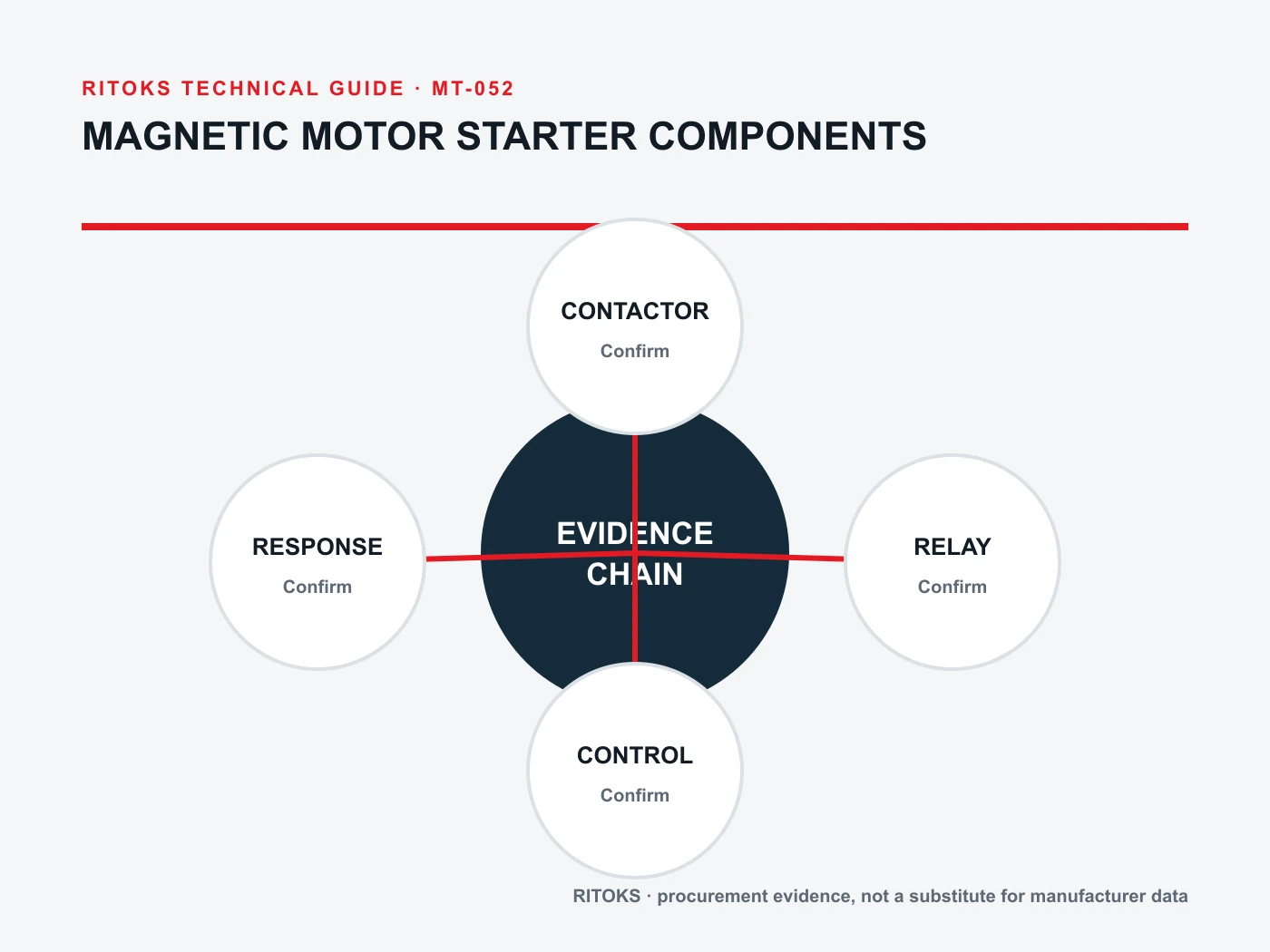
Questions for an enclosed-starter inquiry
Provide motor nameplate details, supply voltage and frequency, starting method, expected duty, control supply, operating environment and short-circuit data. State which accessories are required: auxiliary contacts, indication, pushbuttons, interlocks or remote controls. Ask whether the quoted starter includes an overload function and short-circuit protection or expects upstream devices supplied by the panel builder.
Request the exact circuit diagram, component order codes, overload range, control wiring, enclosure drawing and installation instructions. If the assembly is offered with optional devices, identify which configuration is quoted. A broad starter-family photograph cannot answer whether the delivered model has the desired coil, trip range or terminals.
The motor starter category and ZSLE1-D enclosed magnetic starter page provide commercial context. Review the contactor and overload functions as an assembly rather than assuming compatibility with an arbitrary replacement. Send the documented requirements through RITOKS contact.
Maintenance and substitution boundaries
When replacing a failed component, confirm the original function and exact configuration. A contactor with the same frame size may use a different coil voltage or auxiliary-contact arrangement. An overload relay with a seemingly similar adjustment range may have a different trip characteristic or reset method. A short-circuit device change may invalidate coordination evidence.
Retain the approved starter schematic and component list in the panel file. Record settings and test results after installation. If a replacement changes the assembly, route it through design review rather than treating the repair as a like-for-like mechanical swap.
Document the control sequence, not just the power path
Two starters with the same motor-side components may behave differently because their control circuits are different. Define what happens after loss and restoration of control power, how a remote stop interacts with local buttons, and whether an overload trip requires manual reset. The circuit should make the intended restart behavior clear to operators and maintenance staff.
Auxiliary contacts may report contactor state, indicate an overload trip or form an interlock. Their rating and wiring must be checked for the control circuit. A light on the enclosure door may show a commanded state rather than prove that power contacts have opened. Label indications in a way that matches the actual monitored signal. When procurement compares enclosed starters, it should compare these functions as well as the motor current range.
Frequently asked questions
Does a contactor protect a motor from overload?
Not by itself. A separate overload function or an integrated motor-protective device must perform that job in the documented starter architecture.
Is an overload relay a short-circuit breaker?
No. Overload behavior and short-circuit interruption are different functions. Specify the fault protective device and check its relationship to the starter components.
Does an enclosed starter include everything needed?
Only the exact quoted configuration defines what is included. Ask for the schematic, component list and external supply/protection requirements before ordering.
Bottom line
Think of a magnetic motor starter as a coordinated set of functions: controlled switching, overload response, short-circuit protection, enclosure and control logic. Specify each role and demand exact configuration evidence. That makes both first selection and later maintenance safer and more predictable.