
DC Surge Protective Devices · Technical Explainer
PV Insulation Testing with SPDs Connected: Read the Device Instructions

Quick answer
Before PV insulation resistance testing, identify the circuit being tested and every SPD, inverter and electronic accessory connected within that boundary. Obtain the exact manufacturer's instructions, then have the qualified commissioning team define equipment treatment, test voltage, measurement method and acceptance criteria. Neither an SPD's voltage marking nor a combiner's operating rating is permission to apply an insulation test across connected equipment.
Do not use a universal rule such as leaving all SPDs connected, removing every cartridge, or selecting one tester voltage for all PV installations. The correct arrangement depends on the devices, circuit and approved test plan. Document temporary changes and restoration as carefully as the resistance reading itself.
This article is a documentation and procurement workflow. It does not provide a field switching, short-circuiting or connector-removal procedure.
Separate the test objective from the instrument setting
An insulation resistance test applies a test condition to a defined circuit and measures its response. First decide what the result is intended to establish: commissioning evidence for an array section, investigation of an insulation alarm, or verification of a particular cable segment after repair.
These objectives may have different boundaries. A result for disconnected array wiring is not a test of the inverter's internal electronics. A reading taken with additional equipment connected may not be directly comparable with a previous record that excluded that equipment.
The public description of IEC 62446-1 identifies documentation, commissioning tests and inspection for grid-connected PV systems. It supports planning a documented handover rather than collecting isolated readings. Only its public scope description is used here; the full standard and its test clauses have not been consulted for this guide. The responsible team should confirm the applicable edition, amendments and local requirements. IEC 62446-1, public scope description.
Put the objective at the top of the test sheet before choosing an instrument setting. Otherwise, an apparently precise resistance value can conceal an undefined measurement.
Mark the boundary on the actual schematic
Use the current as-built drawing, not a generic combiner illustration. Identify array sections, parallel paths, combiner devices, inverter inputs and any integrated or external surge protection. Include monitoring equipment where it is electrically relevant to the planned measurement.
For each proposed measurement, record which equipment remains inside the test boundary and which equipment is outside it. A switch position alone is not sufficient documentation of the boundary unless the circuit and manufacturer's instructions establish what that position actually separates.
The RITOKS LQX-N combiner box is a useful starting point for requesting the supplied configuration drawing and device references. Its family page does not determine a site-specific insulation-test method or prove that every connected circuit is separated by one switching action.
Where several drawings disagree, resolve the discrepancy before authorising the test. Record changes discovered during the walkdown so the final measurement can be traced to the installed system rather than the purchase-stage concept.
Read the SPD instruction, not just its rating label
An SPD intentionally responds to overvoltage. That makes its treatment during insulation testing a device-instruction question, not simply a comparison between two voltage numbers.
A Schneider Electric warning sheet expressly requires the SPD concerned to be disconnected before insulation resistance testing to avoid equipment damage. Its illustrations relate to the arrangements covered by that document; they are not a RITOKS PV wiring procedure. The example shows why an explicit warning can matter more than a catalogue headline. Schneider Electric, NHA43714 insulation-test warning.
For the installed SPD, ask what the manufacturer requires and what physical action satisfies that requirement. A pluggable appearance does not establish that removing one visible module excludes every relevant protection path. Likewise, a thermal disconnector or status indicator is not evidence of an approved test-isolation arrangement.
Use the RITOKS PV DC SPD family or the LT1 PV SPD configuration page to identify the exact reference for a documentation request. Do not infer testing permission, voltage or removal technique from a family URL, pole count or headline rating.
Obtain the inverter's own procedure independently
The inverter manual remains necessary even when an external SPD has been addressed. Confirm the exact inverter model, relevant connected equipment and the task covered by the manual section.
SMA's Sunny Tripower Smart Energy instructions contain a qualified-person task for investigating PV ground faults through insulation resistance measurement. The task requires suitable equipment and gives its own restrictions; it specifically says not to perform that measurement without the required suitable device. That is a model-specific troubleshooting example, not a transferable sequence for another inverter or all PV commissioning work. SMA, insulation resistance measurement task.
The useful procurement lesson is to obtain the relevant task instructions before the site team arrives. A general installation brochure or an inverter's operational insulation-monitoring display is not necessarily the document needed for an external insulation test.
If inverter and SPD instructions appear inconsistent with the proposed method, stop the document approval and seek clarification from the responsible manufacturers and designer. Do not invent a compromise test setting to make the paperwork agree.
Use a device-treatment confirmation table
Prepare a short matrix for each distinct test boundary. It should identify instructions and outstanding decisions, rather than serve as an improvised switching checklist.
| Item in the proposed boundary | Document to obtain | Decision requiring confirmation |
|---|---|---|
| PV modules and array section | Exact module documentation and approved array test plan | Permitted method and relevant module limitations |
| External SPD | Exact reference installation or service instruction | Whether and how the device must be excluded or treated |
| Combiner assembly | Supplied schematic and component schedule | Actual protection paths, switching boundaries and auxiliary connections |
| Inverter | Exact model manual and relevant test or service task | Required equipment treatment and task-specific restrictions |
| Monitoring or electronic accessories | Exact equipment instructions | Whether the proposed test can reach sensitive circuits |
| Test instrument | Instrument manual and valid equipment records | Suitability for the PV conditions and selected method |
Attach document revisions or dates to the matrix. Record a manufacturer clarification as a referenced response, not an undocumented verbal assurance. An unresolved cell is a planning hold, not permission for the technician to select a familiar setting.
Approve voltage and acceptance criteria together
The test voltage is only one part of the method. Record the measurement arrangement, required duration or observation basis, acceptance criteria and the source that authorises them for the defined task.
Do not choose a setting solely because it is below an SPD's maximum continuous operating voltage. That marking concerns the device's service conditions, not a general approval for applying an insulation test to the connected assembly. Nor does a high component voltage rating establish that inverter electronics tolerate the same test.
Where the method changes because equipment is excluded or a different boundary is tested, identify the change in the report. A number without its method cannot establish equivalence with a prior measurement or satisfy an acceptance criterion chosen for a different circuit.
The commissioning lead should also identify what an unexpected or unstable result means for the next decision. The answer may be a controlled investigation under the approved procedure, not repeated tests at increasingly severe settings. Keep the raw observations so later review can distinguish the original result from the follow-up work.
Assign the work to a PV-competent team
Insulation testing introduces its own test voltage, while PV circuits and connected energy sources require a task-specific safety plan. Treat equipment isolation and test preparation as engineering work, not a routine consequence of turning off a display or selecting an inverter standby mode.
HSE's electrical safety guidance emphasises competence, manufacturer instructions, control of all energy sources and stored energy, prevention of reconnection, and proving conductors dead where applicable before work on exposed conductors. These are general safety principles, not a complete PV test method. HSE, electrical safety FAQs.
The team must determine the safe working arrangement for the actual PV task, including the sources that remain relevant under its environmental and operating conditions. This guide does not authorise live access, makeshift string shorting, connector opening under load or bypassing a manufacturer's restriction.
If required instructions or suitable equipment are missing, postpone that test activity and resolve the gap. A commissioning deadline is not evidence that a different procedure is acceptable.
Make restoration part of the handover
Temporary exclusions create a second documentation obligation: confirm the intended operating configuration has been restored. The test sheet should identify every authorised change and its closure evidence.
Do not let a passing insulation reading become the only release condition. It describes the defined tested circuit, not whether omitted surge protection has been reinstated, monitoring has been restored, or a discovered drawing discrepancy has been resolved.
| Handover field | Useful record | What it prevents |
|---|---|---|
| Circuit identity | Array, string or segment reference matched to drawing | A result being assigned to the wrong circuit |
| Tested configuration | Included and excluded equipment with instruction references | Comparing readings from different boundaries as equivalent |
| Instrument and method | Equipment identity, settings and approved procedure | A resistance number without reproducible context |
| Observations | Raw reading and relevant recorded conditions | Losing evidence when follow-up measurements differ |
| Temporary changes | Authorised changes and restoration record | Protection or monitoring remaining unintentionally excluded |
| Release decision | Reviewer, unresolved defects and acceptance basis | Treating a single test as approval of the whole installation |
A compact record with these fields is more useful than a long list of resistance values whose configurations are unknown.
Ask suppliers for commissioning documents before ordering
Include insulation-test documentation in the RFQ deliverables. Request exact device references, assembly schematics, applicable SPD instructions and the relevant inverter integration requirements. Ask whether commissioning access or equipment treatment creates design considerations that should be resolved before shipment.
This is especially important when substitute components are proposed. Two SPDs with similar headline electrical ratings may have different construction, instructions or service arrangements. Accepting a substitute should include reviewing its effect on the approved test plan, not just updating the purchase price.
For an EPC handover, separate responsibilities clearly: the supplier provides accurate product and assembly information, while the responsible designer and competent commissioning team establish the applicable site method and acceptance. A commercial page is an enquiry route, not a signed test procedure.
Fill the treatment record before interpreting a result
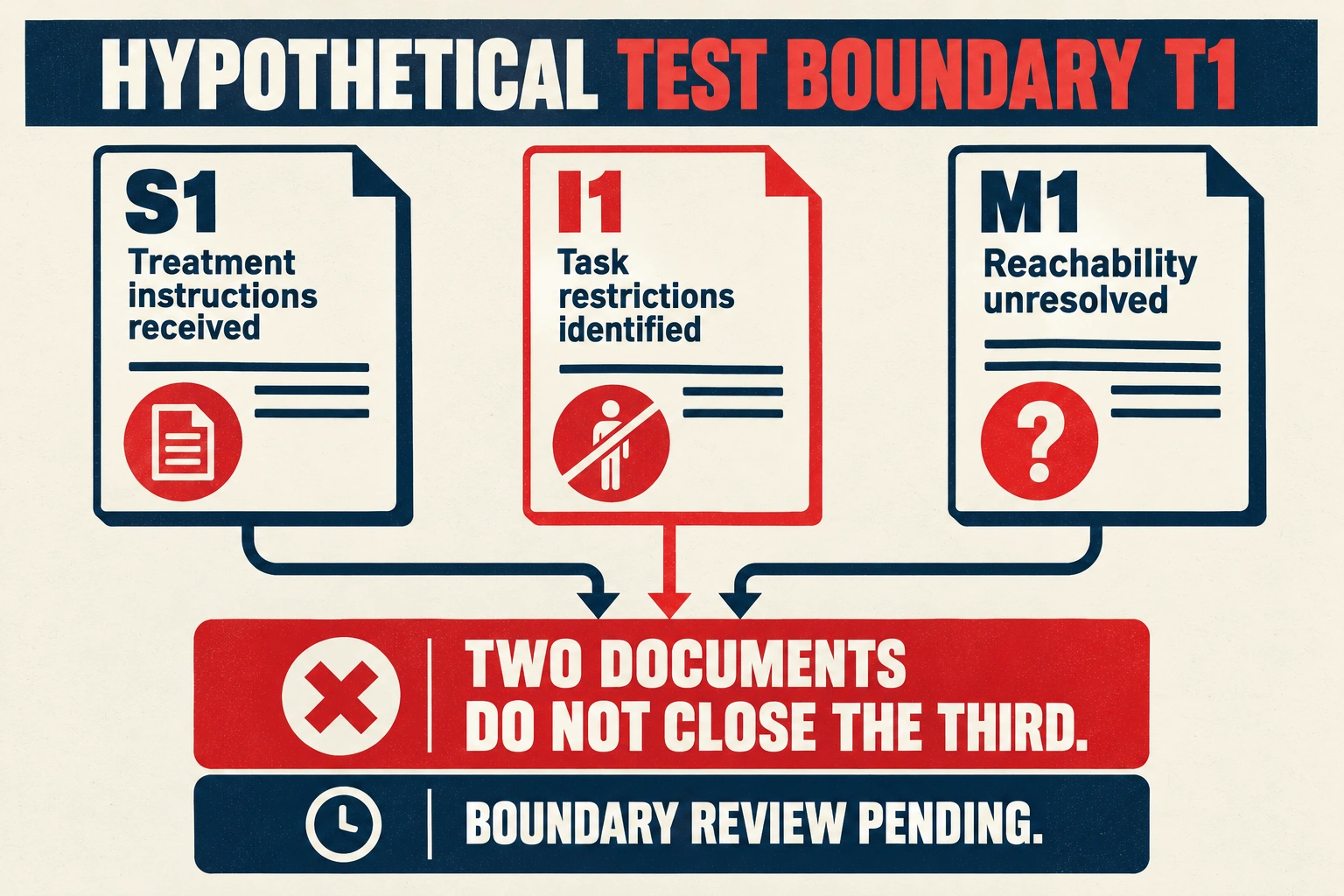
Consider a hypothetical commissioning file T1 for array section A1 on drawing D2. Its device schedule names external SPD S1, inverter I1 and monitoring accessory M1. These identifiers and the following documents are fictional; they are not a RITOKS procedure, real test report or instruction to operate equipment. The proposed objective is insulation evidence for a defined array section, not evaluation of all electronics in the cabinet.
T1's first completed entry reads “S1: exact instructions received; exclusion required under the described task; proposed boundary must account for the complete applicable protection arrangement.” Its second reads “I1: exact manual received; relevant task and equipment restrictions identified.” Its third reads “M1: test reachability and treatment unresolved.” The useful finding is that documentation for two devices does not close the third. The commissioning lead should resolve M1 and the boundary before approving this activity, rather than treat a familiar instrument setting as a substitute for its missing instructions.
Suppose an authorized clarification establishes that M1 is outside the proposed measurement boundary under drawing D3. That can close the reachability question for D3, provided the actual assembly corresponds to it. It does not erase the manufacturer's treatment requirements for S1 or I1. Conversely, if the clarification shows M1 remains inside the boundary and forbids the proposed test condition, the method needs revision. These are different outcomes from the same inquiry; a list saying only “manuals collected” would miss the decision.
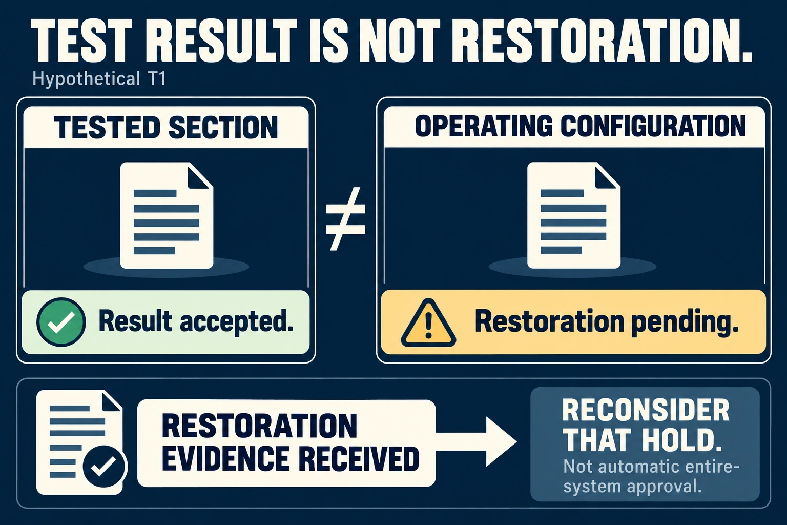
Now imagine the qualified team completes an approved measurement and records that its applicable acceptance criterion was met. T1 still contains an open restoration entry for S1. The file may therefore contain an accepted result for the tested section while operating-configuration release remains pending. No resistance number is invented, and the example does not prescribe the temporary action that produced the tested configuration. It simply separates the meaning of the measurement from the evidence that excluded protection was restored.
When the restoration record is completed under the approved plan, the release reviewer can reconsider that particular hold. If the restored component reference differs from S1, the original instructions and configuration finding may need review instead of a simple closure mark. A procurement substitution made after method approval can therefore affect commissioning documents even when its catalogue voltage appears unchanged.
This creates a practical design tradeoff. A clearly documented boundary may make the required task easier to plan and repeat, but any equipment exclusion introduces treatment and restoration responsibilities. Leaving additional devices in the boundary can reduce temporary changes only if their exact instructions permit the method. Neither choice is justified merely by convenience. The completed file should preserve the objective, boundary, approved treatment and restoration outcome so a later reviewer can see which decision changed and why.
References
- IEC. (2016). IEC 62446-1: Public scope description. Public abstract only; full standard not consulted. Accessed October 2, 2026.
- Schneider Electric. (2021, May). NHA43714-01: SPD insulation resistance test warning. Manufacturer example, not RITOKS PV instructions. Accessed October 2, 2026.
- SMA Solar Technology. (n.d.). Check the PV system via insulation resistance measurement for ground faults. Specific Sunny Tripower Smart Energy task. Accessed October 2, 2026.
- Health and Safety Executive. (n.d.). Electricity: Frequently asked questions. Competence and safe-work sections. Accessed October 2, 2026.