
Electrical Measurement & Monitoring · Technical Explainer
Modbus Energy Meter Values Look Wrong: Check Data Type and Byte Order

Quick answer
When a Modbus energy meter responds but the platform displays an implausible value, preserve the raw registers before changing the meter. The application may be reading the wrong location, interpreting the right bits with the wrong data type, assembling multiple words in the wrong order, or applying the wrong unit conversion. A valid response alone cannot identify which interpretation is correct.
The useful deliverable is a decoding record: exact meter and firmware, register-map revision, request, returned words, interpretation settings and a contemporaneous local reading. This record lets the integrator distinguish communication success from measurement meaning. It also gives purchasing a specific documentation request rather than a vague complaint that Modbus does not work.
The RITOKS 2P RS485 Modbus energy-meter family and multifunction digital power-meter family are relevant enquiry destinations. Obtain the exact offered variant's register map. This article supplies no register addresses, byte order or multiplier for those families without matching documentation.
Freeze the register-map identity first
Record the complete model, communication option and firmware information available from the unit or supplier. A family catalogue may describe several configurations while a register document applies to one revision. Keep the document title, revision and date with the commissioning configuration so later substitutions do not silently inherit an unverified map.
Choose one clearly defined measurement for the initial comparison. State whether it is voltage, instantaneous power, interval demand or accumulated energy. Similar names can refer to different quantities or aggregation boundaries. A platform tag called total power does not prove that its assigned register contains the intended field.
Request the register's function, starting address, length, data type, unit, scale and validity conventions. Include the address notation used by the client. Where the manufacturer provides a sample response, retain it as a reference for the documented device rather than assuming the sample describes every meter with Modbus communication.
Do not resolve an unclear map by writing to possible configuration registers. Keep the initial investigation read-only and use the documented read function. A guessed write could change measurement configuration, reset an accumulator or affect an available control function. The meter's role in the installation makes that a different, separately authorized task.
Separate register references from transmitted addresses
A register reference in a manual and the address field sent by a client can use different notation. Some interfaces accept a traditional reference, others accept an offset, and some allow the user to configure the convention. Check both the device documentation and the client's addressing instructions instead of applying an automatic subtraction to every number.
The Modbus Application Protocol specification defines the application data model and request addressing. Its register data model does not identify an energy meter's engineering fields. Those meanings belong to the equipment's map. Keep the protocol location and the manufacturer's variable name as two linked records.
In a hypothetical manual using the traditional holding-register reference 40001 for the first location, a client requiring a zero-based offset may use zero. That is an illustration of notation, not a RITOKS address recommendation. A manual that already lists protocol offsets needs a different interpretation. Record what actually appears in the transmitted request.
Also distinguish the supported read functions. Holding-register and input-register requests are different operations. Do not change the function merely because a familiar number appears in a table. The selected field's documentation determines the operation and permitted range. An exception response is useful diagnostic evidence, not a reason to try unrelated addresses indiscriminately.
Read the declared type before inspecting the magnitude
A Modbus register is a 16-bit quantity, while a device variable can span more than one register. The returned words do not announce whether the application should treat them as an unsigned integer, signed integer, floating-point number or part of a larger accumulator. The register map must supply that interpretation.
Schneider Electric's floating-point conversion guidance explains that some of its energy meters use IEEE 754 floating-point representation and directs readers to the specific map. That supports checking the declared type; it does not establish the type used by an unidentified meter. Never transfer a Schneider address or format to a RITOKS variant on that basis.
An integer may need a documented multiplier to become an engineering value. A float can already represent an engineering quantity, but its unit still matters. Signed and unsigned interpretations can differ substantially for the same bits. Do not pick whichever interpretation looks plausible at one operating point and call that a confirmed configuration.
Read the documented complete value as a group where the device supports that operation. For a changing multiword quantity, separate reads may capture parts from different updates. Ask whether the device provides coherent reads or another defined acquisition method. Do not assume an arbitrary block size or polling strategy guarantees a consistent snapshot.
Distinguish byte order from word order
Byte order describes how bytes form a word; word order describes how multiple register words form a larger value. The protocol's representation of a 16-bit register and the manufacturer's arrangement of a multiword variable are related but different questions. A client can expose separate options for swapping bytes and swapping words, so record each option explicitly.
The Modbus Organization's introduction notes that manufacturers do not all split 32-bit floating-point values into register words in the same order. Use that as the reason to obtain the device's multiword convention, not as permission to change every combination until the screen looks reasonable.
For a hypothetical four-byte value, define A, B, C and D as bytes in the intended most-significant-to-least-significant representation. An interface might describe sequences such as ABCD or CDAB, but another tool may label its options differently. Translate the tool's description back to actual byte positions. A checkbox labelled little endian is insufficient evidence without its documented effect.
Keep the original returned words beside the reordered bytes and decoded result. That makes a configuration reproducible across PLC, gateway and platform software. If two clients disagree, compare their interpretation records rather than assuming that the meter changed its output between them.
Work through a deliberately hypothetical example
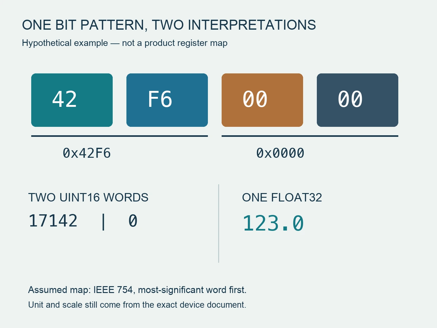
Assume a teaching example with two returned registers: 0x42F6 followed by 0x0000. Further assume the device map declares a 32-bit IEEE 754 float with the most-significant word first. Assembling the bytes as 42 F6 00 00 gives 123.0. This example is constructed for explaining interpretation and is not a captured response from either linked product.
The same two words, viewed as separate unsigned 16-bit integers, are 17142 and zero. Reversing their word order produces a different bit pattern, not a legitimate alternative measurement merely because a decoder returns a number. The declared type and ordering are what make 123.0 the intended teaching result.
| Interpretation layer | Hypothetical evidence | Meaning |
|---|---|---|
| Raw response words | 0x42F6, 0x0000 | Preserve before conversion |
| Documented assembly | 42 F6 00 00 | Most-significant word first in this example |
| Documented type | IEEE 754 float32 | Bit interpretation, not integer conversion |
| Decoded value | 123.0 | Still needs the documented unit |
The example deliberately omits a unit. If the map says watts, the result means watts; if it says another supported quantity, the meaning changes accordingly. A decoder cannot discover the engineering unit from these bits. Attach that information from the exact register document before exporting the value to a dashboard.
Now fill a hypothetical integration record rather than merely select a swap option. Document D1 defines this constructed float field as watts, and gateway configuration G1 uses the declared most-significant-word-first interpretation. G1 reports the teaching value as one hundred and twenty three watts. Platform configuration P1 then applies a multiplier intended for a different integer field. The raw words and gateway interpretation have not changed; the platform conversion is the changed layer. A supplier request about meter byte order would miss the actual discrepancy in this fictional chain.
Assume the mistaken multiplier is one hundredth. It turns the decoded value into one point two three while P1 continues to label it watts. The filled disposition is “documented decoding retained; platform scale conflicts with D1,” not “meter inaccurate.” Removing that extra multiplier would reconcile this constructed chain with D1, but the project still needs contemporaneous comparison evidence before accepting its real integration. No captured meter reading or performed configuration change is claimed here.
A different hypothetical revision D2 changes the field definition to a scaled integer. G1's earlier float interpretation would then lose its documentary basis even if one displayed number happened to resemble the local display. The accepted configuration must follow the exact offered map revision, not a preferred decoder setting. This reverses the earlier decision about which layer needs correction: with unchanged D1 the platform scale was wrong; with changed D2 the gateway interpretation also needs review. Keeping returned words, map identity and each conversion separate makes that difference visible.
Finally, suppose client C2 reads a different documented measurement than G1, while both use valid transactions and correct encoding for their own fields. Their disagreement is not evidence of competing byte orders. The reviewer first reconciles field identity and unit, then compares the interpretation chain. This filled example allows valid work to remain accepted while the affected field or conversion is reopened. Trying swaps until two screens agree could hide the mismatch and produce a coincidence that fails at another operating condition.
Apply scaling once and preserve the unit
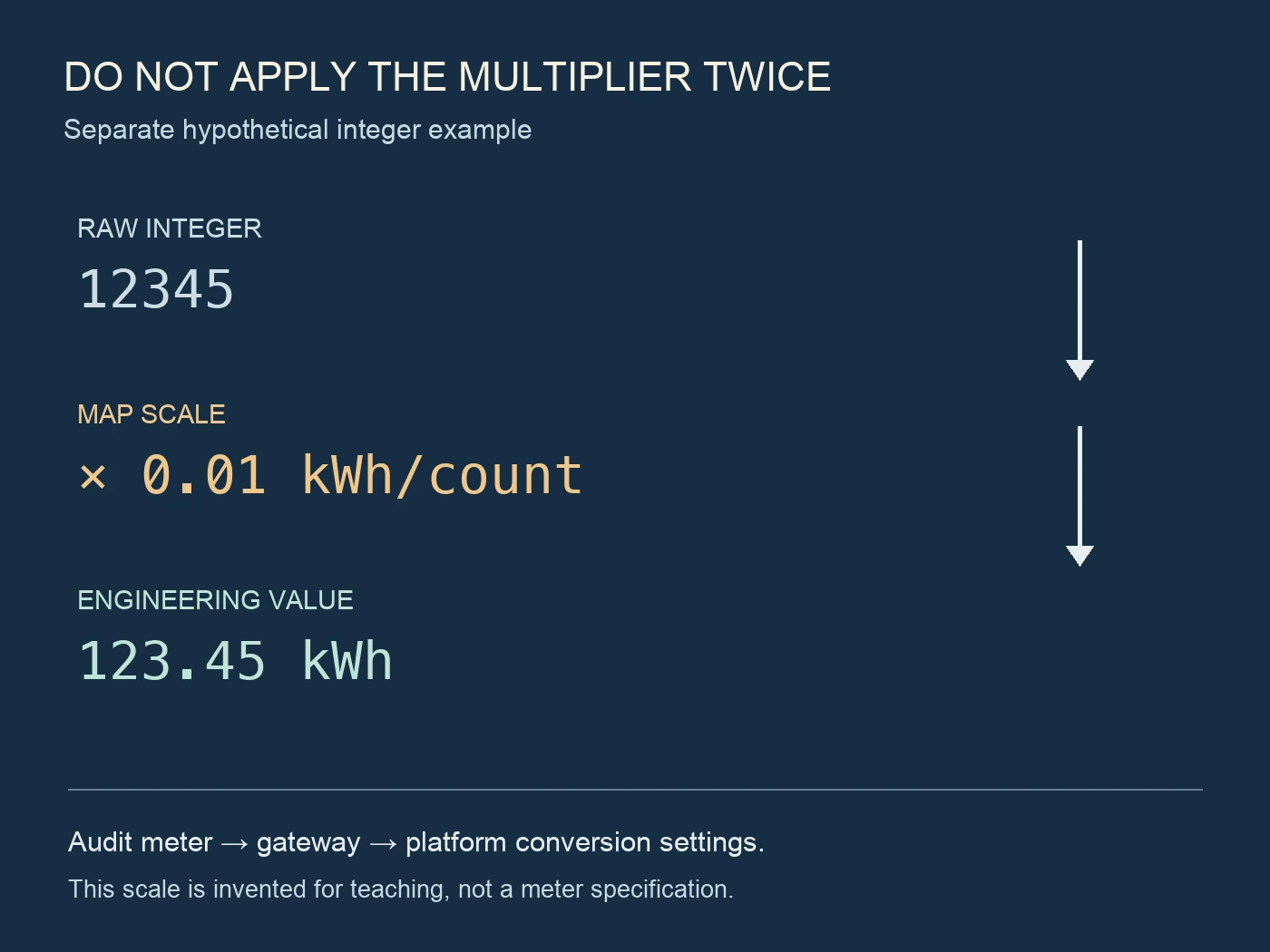
After decoding, identify every conversion between the register and the displayed tag. The meter may report a scaled integer or a value in a particular unit, while the gateway and platform can each have their own multiplier. Write the chain explicitly so the same conversion is not applied twice.
For a second hypothetical example, suppose a documented integer field returns 12345 with a scale of 0.01 kWh per count. Its engineering value is 123.45 kWh. This is separate from the float example above. Do not use that scale for a real product unless its map specifies it, and do not multiply again simply because the platform includes a scaling field.
Distinguish display settings from communication representation. A local display may show fewer decimals, use a prefix, or expose a different field from the selected register. Record the display label and unit as well as its number. A numerical mismatch can be a field or unit mismatch even when the byte interpretation is correct.
For accumulated energy, request documented rollover, reset and invalid-value behavior where relevant. A sudden change could reflect those semantics rather than an endian problem. Preserve status information and timestamps so the investigation does not reduce every unusual value to byte swapping.
Compare a small set of known operating states
Validate the proposed interpretation using several documented readings under controlled, authorized conditions. Capture the local field and register response as closely in time as practical. Changing load and update intervals can make readings from different times incomparable. Note that limitation instead of forcing the decoded value to match an old photograph.
Check whether direction and signed quantities behave as the map describes. A small positive reading alone may not reveal a signedness error. Only use operating cases the installation can safely and legitimately provide; do not create an electrical condition solely to test an unsupported assumption.
Separate a missing or stale response from an unusual measurement. The platform should retain communication validity and the age of the last successful read. Carrying a previous value forward without marking it stale can resemble a frozen meter. A decode review and a communication-quality review have different evidence boundaries.
Hand over an interpretation record, not a guessed setting
The final integration record should include the exact map, read function, client address convention, register count, returned example words, data type, byte and word order, scale, unit and validity handling. Add the comparison readings and the configuration revision used for acceptance. Keep unresolved fields visible for the supplier or integration owner.
When requesting support, send one compact raw-response example with its request and expected field. Avoid screenshots that show only the final dashboard number. The supplier can assess the interpretation far more precisely when the original words and map row remain available.
Release the configuration when the evidence supports the whole chain from requested location to engineering value. A plausible number is a useful clue, not acceptance by itself. The result should remain reproducible after a software update or meter replacement without relying on someone remembering which swap checkbox happened to work.
References
- Modbus Organization. (n.d.). Modbus Application Protocol Specification V1.1b3, sections 4.2–4.4. https://www.modbus.org/file/secure/modbusprotocolspecification.pdf
- Modbus Organization. (n.d.). Introduction to Modbus. https://www.modbus.org/introduction-to-modbus
- Schneider Electric. (n.d.). Floating-point conversion guidance, FAQ FA204140. https://www.se.com/ca/en/faqs/FA204140/