
Diode Rectifier Modules · Technical Explainer
Anti-Reverse Diode Modules: Function and Selection Boundaries
An anti-reverse diode module is used in a defined current path to block an undesired reverse-current condition. That simple functional description does not select the device. The engineer must define normal current, reverse voltage, transients, forward loss, thermal path, circuit configuration and the consequence of a diode failure.
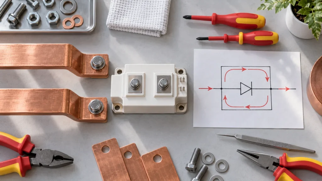
This article explains selection boundaries for industrial diode modules used in reverse-current blocking roles. It does not provide a wiring design, claim that every rectifier module is suitable for reverse-polarity protection, or transfer Infineon small-signal circuit examples to RITOKS high-power modules.
Buying Decision at a Glance
| Decision input | Buyer must confirm | Evidence required |
|---|---|---|
| System role | Reverse connection, source backfeed or another defined reverse-current event | Circuit diagram and fault narrative |
| Forward path | Continuous, cyclic and surge current under normal operation | Exact current and forward-voltage data |
| Blocking stress | Steady and transient reverse voltage | Exact repetitive/non-repetitive voltage data |
| Thermal path | Calculated forward loss, sink, interface and ambient | Exact thermal-resistance and mounting data |
| Configuration | Single, common-anode, common-cathode or other internal circuit | Terminal diagram for the exact module |
Name the Reverse-Current Problem
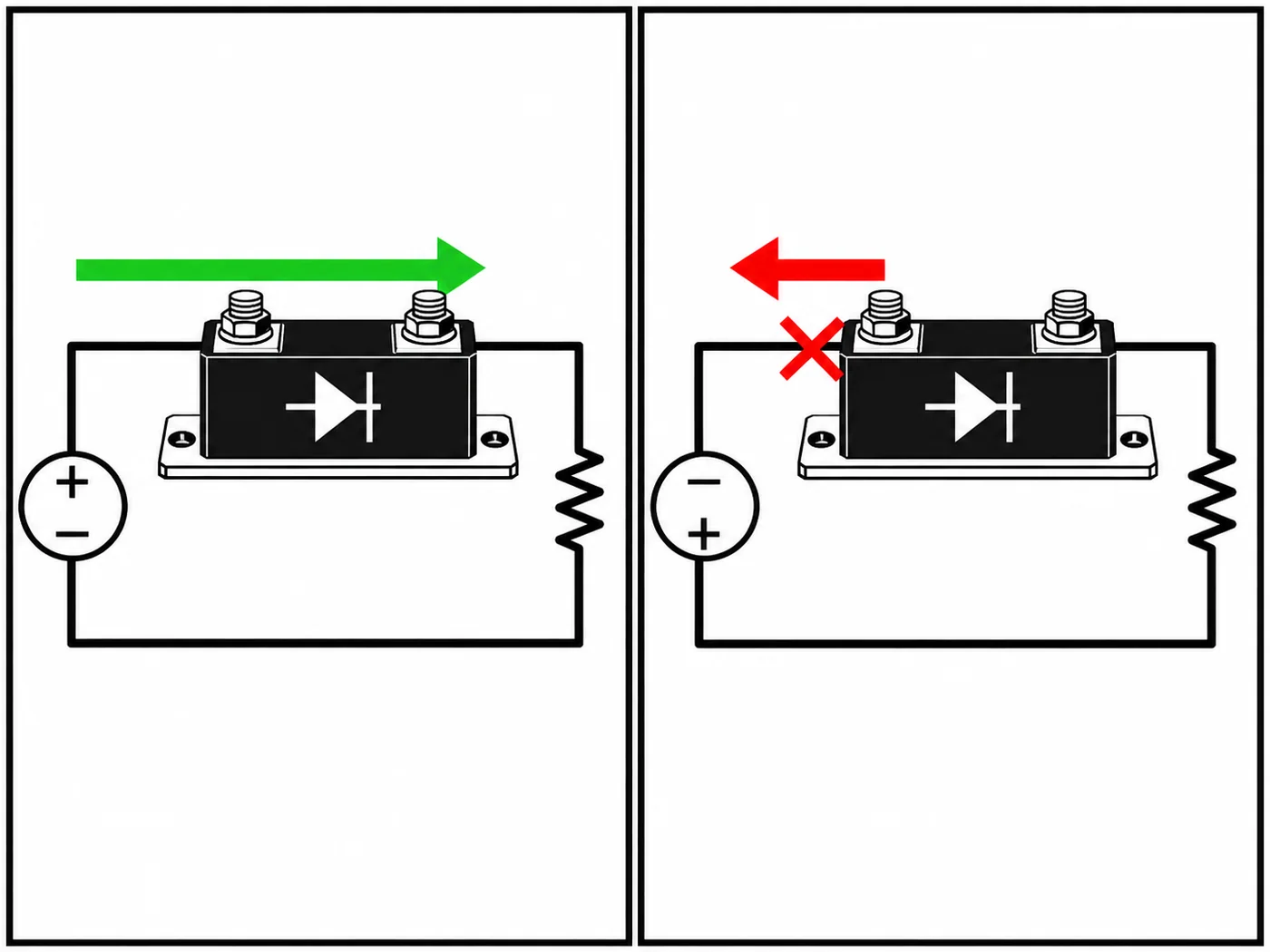
Reverse polarity, reverse battery connection and backfeed between sources are not automatically the same event. Draw the expected current direction during normal operation and the path that must be blocked during the abnormal condition. This identifies where a series diode may help and what voltage it must withstand.
Also describe how the system should behave during the event. A blocking diode can stop current in one direction, but it does not automatically disconnect every energy source, limit a surge or make the equipment continue operating.
Calculate Forward Loss in Normal Operation
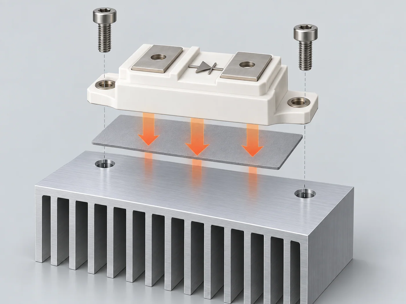
A series diode carries the normal load current, so its forward voltage creates power loss and temperature rise. Use the exact module forward-characteristic data at the relevant current and temperature. A room-temperature typical value is not a worst-case thermal design.
Check continuous current, duty cycle and expected overload or inrush separately. The module current headline may depend on a specified case temperature or cooling condition. Keep those conditions with the rating.
Define Reverse-Voltage Stress
Record the highest steady reverse voltage and credible transient stress across the diode. Compare them with the correct repetitive and non-repetitive data for the exact module, using the manufacturer’s definitions and required margin.
Do not use a forward-current rating as evidence of reverse blocking. Likewise, a large reverse-voltage number does not prove adequate surge-current or thermal performance. Each stress needs its own documented characteristic.
Confirm the Internal Circuit and Terminals
Diode modules can contain different internal arrangements, including common-anode, common-cathode, series or bridge configurations. The external package may look similar while the current path is different. Verify the terminal diagram and marking before approval.
The MDA and MD300A pages represent different published product records. Product proximity does not make their circuits interchangeable. The proposed order code, internal diagram and terminal identification must remain together through quotation and inspection.
Keep Other Protection Functions Separate
A blocking diode is not automatically a fuse, surge protective device, disconnect, reverse-energy clamp or controlled ideal-diode function. Define short-circuit protection, transient suppression, isolation and safe shutdown elsewhere in the system design.
Consider the failure modes relevant to the application. If an open or shorted diode creates a hazardous state, the design may need monitoring or redundant measures. Those decisions belong to the responsible system engineer and applicable standards.
Build an Evidence File Before Approval
Create one review sheet for the proposed Diode Rectifier Module order code. Put project inputs in one column and supplier evidence in the other. Preserve the exact pages, drawings, curves and tables used in the decision, including their revision or retrieval date. A category page can establish product-family context, but an exact rating or connection claim must trace to the quoted configuration.
Check that every accepted value describes the same orderable item. Similar housings can contain different circuits, supplies, terminals, airflow arrangements or accessories. Do not combine a family maximum from one variant, a drawing from another and an optional feature from a third. Mark unresolved fields explicitly instead of allowing them to disappear in the commercial quotation.
Control Changes During Sourcing
Keep the application record frozen while suppliers respond. If the load, voltage, environment, duty, enclosure, cooling method or required output changes, issue a revised record and ask each supplier to reconfirm the candidate. Otherwise two quotations may look comparable while answering different technical requirements.
A proposed substitute returns to the same evidence gate. Matching dimensions, a similar product photograph or one equal headline rating is not enough. The substitute must satisfy the required functions and conditions with its own exact documentation.
Common Procurement Errors
- Selecting Diode Rectifier Module from one headline rating while leaving the application context undefined.
- Using a curve, terminal diagram or performance claim from a neighboring model.
- Comparing free-air, nominal or family-maximum data with an application operating point.
- Treating included accessories and system functions as obvious from a product name.
- Approving a substitution without reopening the technical evidence review.
Resolve these gaps before comparing price and lead time. The reviewer should be able to trace each accepted statement either to the project requirement or to the exact candidate document. This prevents a lower-cost but narrower offer from appearing equivalent to a complete solution.
How to Compare Supplier Offers
| Comparison point | Required evidence | Do not accept |
|---|---|---|
| Function | Exact undesired current path identified | Generic “reverse protection” label |
| Forward duty | Current waveform and loss calculation | Family maximum current |
| Reverse stress | Repetitive and transient voltage checked | Nominal system voltage only |
| Circuit | Internal diagram and terminals verified | Package appearance |
| Protection scope | Fuse, surge and isolation roles allocated | Diode assumed to cover every fault |
Normalize every Diode Rectifier Module offer to the same application record. Keep document revisions, test conditions and open questions beside each value. A proposal can remain commercially interesting while technically incomplete, but missing evidence must stay visible until it is resolved.
Decision Workflow
- Draw normal and abnormal current paths.
- Define continuous, cyclic and surge forward current.
- Define steady and transient reverse voltage.
- Verify the exact internal circuit and terminals.
- Calculate forward loss and the complete thermal path.
- Review failure behavior and all separate protection functions.
At each step, preserve the boundary between project inputs and manufacturer evidence. The project team defines the application and required functions; the supplier identifies an exact product and supports it with documents. Neither side should fill a gap by inference from appearance or a shared headline rating.
RFQ Preparation Checklist
A useful RFQ for anti reverse diode module is concise enough to answer and complete enough to prevent silent assumptions. Identify unknown values as questions and require an exact orderable code rather than a generic family recommendation.
- System schematic and reverse-current scenario
- Normal current, duty cycle and inrush/surge current
- Maximum steady and transient reverse voltage
- Required internal diode configuration
- Cooling, interface and ambient conditions
- Exact model curve, circuit and dimension drawings
- Quantity and destination
Request the current datasheet revision and the scope of any certification, compatibility or performance claim. Record quantity and destination after the technical inputs so commercial terms do not obscure unresolved engineering questions.
Stop Conditions Before Order Release
Do not release the order while a critical application input is unknown, the quoted model is ambiguous, a required rating is supported only by another manufacturer’s document, or installation conditions fall outside the available evidence. These are engineering gaps, not editorial details.
The approval record should state what the selected item does, what remains outside its scope and which exact documents support the decision. If the application or candidate changes, reopen the affected checks rather than carrying the previous conclusion forward.
Frequently Asked Questions
Is an anti-reverse diode the same as a fuse?
No. It blocks current in one direction but does not automatically provide overcurrent interruption.
Can I choose the module from system voltage alone?
No. Forward current, surge, loss, thermal conditions, reverse voltage and circuit configuration all matter.
Are common-anode and common-cathode modules interchangeable?
No. Their internal connections and terminal behavior differ. Verify the exact circuit diagram.
Related RITOKS Products and Guidance
Use these links as separate category and product records. A contextual link does not claim interchangeability, compatibility or an approved system combination.
Diode Rectifier Module product category
MDA common-anode diode modules
MD300A anti-reverse diode modules
Technical References
These primary manufacturer sources support only the general concepts identified below. Their product values, diagrams and approvals do not transfer to RITOKS products.
Infineon, Application Notes: Reverse Polarity Protection Overview
Supports the system function of a series diode in blocking reverse current and the importance of forward-voltage loss. Infineon circuit examples are not RITOKS module ratings.
Infineon, General-purpose Diodes
Supports the existence of different diode configurations and the need to distinguish circuit arrangement. Listed small-signal ratings do not describe industrial RITOKS modules.
Request an Exact-Model Review
Send the application requirements, exact documentation questions, quantity and destination through the RITOKS contact form. An RFQ requests an exact-model review; this guide does not approve a wiring design, installation or automatic substitute.