
Diode Rectifier Modules · Comparison
Common-Anode vs Common-Cathode Diode Modules: Topology Verification
Common-Anode vs Common-Cathode Diode Modules: Topology Verification starts with the system question: How should terminal and circuit diagrams determine topology? A useful selection brief connects the equipment duty, installation and receiving system to a specific orderable product. The article below separates project inputs from product evidence so that a familiar product name does not quietly become a technical approval.
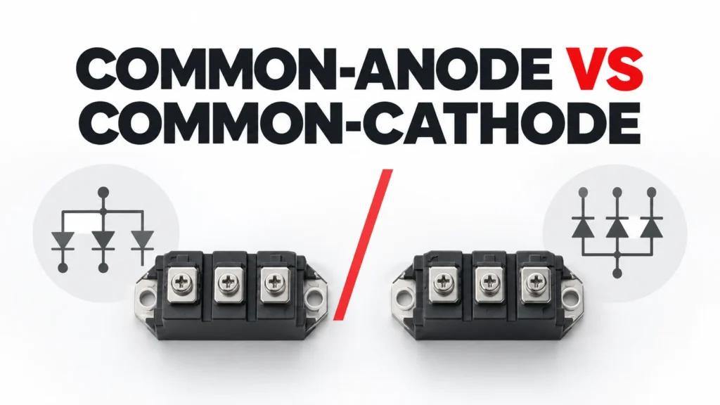
This article compares conceptual common-anode and common-cathode arrangements. It does not identify an exact RITOKS terminal map, approve interchangeability or claim a particular anti-reverse module has either topology without its exact circuit diagram.
Decision Inputs at a Glance
| Review area | Project input | Evidence to request |
|---|---|---|
| COMMON ANODE | Define actual operating state and system boundary | Approved system drawing or duty record |
| COMMON CATHODE | Name interface, geometry or control expectation | Exact equipment or product document |
| TERMINALS | State environment and installation condition | Site or panel drawing |
| CURRENT PATH | Describe service and acceptance requirement | Exact instructions and test plan |
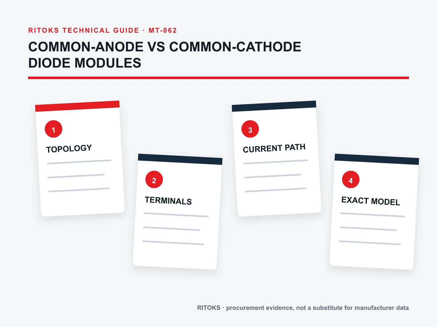
Topology is a circuit relationship
A common-anode diode module joins the anodes of two diode paths at a shared node. A common-cathode module joins the cathodes. This difference changes how the module can be placed in a circuit. The phrase describes an internal electrical relationship; it does not tell the engineer the external terminal numbering, package size or allowable operation of a specific device.
The reliable starting point is the exact manufacturer circuit symbol drawn beside the terminal map. A product photograph may show a familiar package, but the internal wiring can differ. Procurement should use the complete order code to request the drawing and refuse to infer topology from housing shape.
Read the circuit diagram before terminal labels
Identify each diode direction on the exact diagram, then follow every path to a numbered external terminal. Map the common node, the separate nodes and the intended current path in the project schematic. A symbol oriented differently on two datasheets can make the same words feel reversed, so check arrowless diode symbols carefully against polarity and terminal numbers.
If a drawing is ambiguous or the module has optional terminals, obtain a written clarification. Do not use continuity checks on an unknown part as a substitute for an approved design record. Bench checks can support incoming verification, but the design decision belongs to exact documentation.
Translate topology into the application circuit
A common node can be useful in rectification or routing arrangements, but usefulness depends on the surrounding source, load and commutation path. State the intended circuit function before searching for a module. A common-anode part cannot be swapped for a common-cathode part simply by moving a lead unless the whole circuit has been redesigned and validated.
Draw the actual source polarities, current direction in each operating state and what happens during reverse or transient conditions. Then place the candidate internal diagram on that schematic. If the current path cannot be traced unambiguously, the RFQ is not ready.
Separate topology from anti-reverse claims
An anti-reverse product description says what the device may be intended to help prevent in a particular application. It is not itself a complete internal circuit diagram. Verify whether the proposed part is a single diode, dual module or another arrangement and how its terminals are connected. Do not assign common-anode or common-cathode status by association with a nearby category page.
Protection behavior also depends on the whole circuit, including alternate current paths and voltage transients. The system designer must verify the intended result. Keep any claim about reverse-current blocking tied to an exact circuit and the proposed module’s supported electrical limits.
Check electrical stress by the operating state
The exact module must be evaluated for forward current, reverse voltage, surge duty and relevant waveform conditions. These values depend on the selected part and its data table. A family range or a headline maximum does not prove that the quoted order code meets all conditions.
Document each operating state and the voltage across each diode path. Include source transitions and fault or maintenance states that the project design considers credible. Where calculation depends on a transient, use the supplier’s specified method or test evidence. Do not manufacture a rating from a generic topology drawing.
Close the thermal and mounting design
A diode module dissipates heat in its current path. Mounting surface, thermal interface, heatsink or cooling method and terminal connection all affect the installed result. Request exact loss or forward-characteristic data and mounting instructions, then evaluate the assembly at the required duty.
A mechanically matching footprint can hide different thermal or electrical requirements. If an alternative order code is proposed, repeat the circuit, terminal and thermal review. Keep the datasheet revision and assembly drawing together in the approval record.
Verify delivered topology before assembly
Incoming inspection should compare the label, full order code, terminal marks and supplier drawing with the approved bill of materials. Preserve the project schematic as the interpretation reference. If the part marking or pinout differs, hold the item for engineering review rather than improvising rewiring on the production line.
Commissioning checks should verify that connections follow the approved diagram and that the system functions under defined operating states. A topology explanation guides the questions; it cannot replace the exact-device evidence and application test.
Build an Exact-Model Evidence File
For the proposed Diode Module, create one approval record with the complete order code, the exact datasheet, the relevant drawing, installation instructions and any curve or test report used for the decision. Date each file or record its revision. A product-family page is useful for discovery, but it does not prove that a particular configuration includes an optional feature or meets a system condition.
Compare every requirement against evidence for the same orderable item. Do not combine a family maximum from one variant with a circuit diagram, accessory list or thermal curve from another. Put unresolved fields in a visible clarification column. If a supplier proposes a substitute, repeat the affected review before approving its technical equivalence.
Keep Project Inputs Separate From Supplier Claims
The project team owns the application record: source and load, operating states, environment, mounting, controls, service and acceptance criteria. The supplier owns the proposed order code and supporting device evidence. Neither side should fill a gap by inference from appearance or a familiar family name. A useful answer can be “data not yet available,” provided that the missing item has an owner and a closure date.
Freeze that record while offers are compared. If the operating duty, cabinet, source, meter, motor or protective architecture changes, issue a revised input sheet and ask each supplier to reconfirm its candidate. This prevents an early quotation from being treated as approval for a later design.
How to Compare Supplier Offers
| Offer item | What to compare | Approval evidence |
|---|---|---|
| Orderable scope | Full code and included accessories | Exact quotation and bill of materials |
| Electrical fit | All applicable operating states | Exact rating, circuit or curve document |
| Mechanical fit | Mounting, terminals and access | Drawing and installation instructions |
| Service plan | Inspection and replacement method | Maintenance instructions |
| Open items | Assumptions, exclusions and exceptions | Written clarification register |
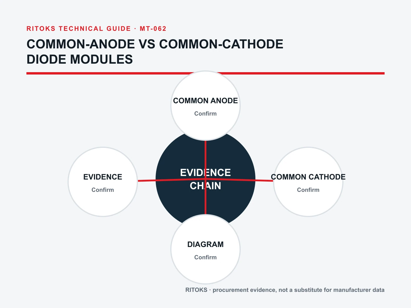
Normalize each Diode Module offer to the same application record. A shorter lead time or lower price is meaningful only after the technical scope is comparable. Record whether each supplier included the required accessories, documents and support for commissioning. Keep exceptions explicit, especially when the candidate needs a change to the panel or control design.
Procurement and Commissioning Checkpoints
- Confirm the system boundary, operating states and acceptance criteria.
- Review one complete order code against exact-model documents.
- Resolve electrical, mechanical, environmental and service exceptions.
- Compare delivered scope and document revisions across offers.
- Inspect the received item against the approved record.
- Test the finished assembly under the project’s authorized procedure.
Incoming inspection should check the delivered label, terminals, included accessories and documents against the approved order. A same-family replacement is not automatically acceptable. At commissioning, verify the application-dependent functions that component literature alone cannot establish. The test plan should name representative states and acceptance criteria without inventing universal limits.
RFQ Preparation Checklist
A useful request for quotation on common anode vs common cathode diode module is concise but complete. Ask for the exact orderable configuration and list unknown values as questions. Do not let the sales description silently answer a technical question that belongs to a calculation, a drawing or a test.
- COMMON ANODE
- COMMON CATHODE
- TERMINALS
- CURRENT PATH
- CIRCUIT
- PINOUT
- POLARITY
- THERMAL
- Applicable document revisions
- Quantity, destination and delivery scope
Request that the supplier state exclusions, assumptions and optional items separately. Keep the technical clarification record with the quotation so procurement and engineering review the same scope. If a critical input is still missing, the candidate may remain commercially interesting, but its technical approval stays open.
Frequently Asked Questions
Can a Diode Module be chosen from one headline rating?
No. The application, exact configuration and relevant electrical, mechanical, thermal and environmental conditions must be reviewed together. A catalog title is a starting point for discovery, not a complete approval record.
Does a family page prove an exact connection or accessory?
No. Use the proposed order code and its current drawing, datasheet and installation instructions. Optional features or alternate terminal arrangements may differ within a family.
What if the supplier cannot provide one required value?
Mark the value unresolved, identify who will obtain it and pause the affected decision. Do not convert an assumption into a verified claim simply because a purchase date is approaching.
Where to Continue the Review
Browse the Diode Module category for the available product family, then review the related product page as a candidate starting point. These pages identify the commercial destination; the exact model documents decide application suitability. For a project-specific comparison, send the system inputs and open questions through the RITOKS inquiry page.
If another device or method appears more suitable after reviewing the evidence, revise the design brief before asking for a substitution. Keep the record tied to the final circuit and installation, not just to the product family that first attracted attention.