
DC Power Protection · Comparison
Panel-Mount vs Cable-Mount PV Connectors: Check the Enclosure Interface
Quick answer
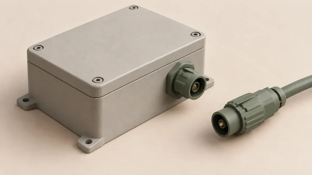
A panel-mount PV connector creates an electrical interface through an equipment enclosure. A cable-mount connector terminates a cable and forms its own connection interface. Choosing between them requires checking the enclosure opening, wall material, fixing, anti-rotation, seals, internal termination and cable loads, not simply comparing connector voltage or current markings.
A panel-mount description does not establish whether the internal termination is a crimped cable, a board interface or another architecture. Likewise, a connector's stated ingress protection does not automatically approve the modified enclosure. Obtain the exact configuration drawings and assembly evidence before releasing the interface design.
This guide is a sourcing and design-review checklist. Opening dimensions, tightening requirements and assembly steps must come from the selected connector and equipment documentation, not a universal PV connector recipe.
Compare the interfaces, not just the product photographs
A panel receptacle can offer a fixed external connection point on an inverter, combiner or other equipment enclosure. Its installation adds a wall penetration, a mounting system and an internal electrical connection. Those interfaces become part of the equipment design.
A cable-mounted connector instead depends on its cable/contact combination, cable entry and completed mating arrangement. If that cable subsequently enters an enclosure through a gland or another feed-through, the enclosure penetration remains a separate interface that must be specified. Choosing a cable-mounted connector does not eliminate the enclosure review.
Start with the intended equipment architecture and service boundary. Identify where the field cable connects, what stays inside the enclosure and which parts can be accessed under the approved maintenance arrangement. Photographs may help identify a family, but they cannot establish mounting tolerances or verified mating compatibility.
The RITOKS RTX-PVC connector and cable-assembly family separates panel/flexible-PCBA references, matched cable pairs, branches and extensions. Treat these as configuration-specific enquiry options. Do not transfer one panel reference's published ratings or presumed construction to all cable assemblies.
Obtain the mounting drawing before releasing the enclosure
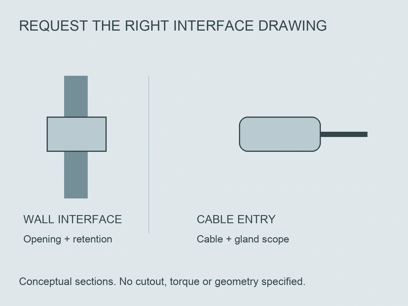
For a panel-mounted option, request the exact opening geometry, tolerances, allowed wall construction and relevant mounting information. Record the connector variant and drawing revision alongside the enclosure drawing.
An opening is more than a diameter. Anti-rotation features, surface condition, wall thickness and access for the fixing arrangement can affect the selected interface. A circular opening copied from another receptacle is not necessarily an acceptable substitute for a shaped opening.
Stäubli's MA299 instructions illustrate this distinction with panel-receptacle openings that differ according to anti-twist functionality. Its mounting notes also address housing material and wall-thickness validation. This is a specific manufacturer example, not a dimensional specification for RTX-PVC. Stäubli, MA299 panel-receptacle instructions.
If the drawing and a written note appear inconsistent, obtain clarification for the exact application. Do not select whichever limit makes the existing enclosure easier to use. Keep the agreed interpretation with the design record so production follows the same approved basis.
Check fixing and anti-rotation as separate functions
The fixing method retains the connector in the panel; anti-rotation addresses a different mechanical behaviour. Confirm how each function is provided in the selected design and how the enclosure participates in it.
Do not assume a tightened nut establishes anti-rotation for every connector. Equally, a shaped opening does not by itself prove that the complete fixing and sealing arrangement is correct. The selected manufacturer's instructions should define the mounting system and relevant inspection criteria.
Consider the loads introduced by external cable routing and mating access. A connector mounted on a thin unsupported area may present a different design problem from the same connector installed in the evaluated panel construction. The equipment designer must assess the actual interface rather than treating the connector as mechanically independent of the wall.
MA299 states that the appropriate mounting torque needs verification for the chosen end-use housing. Its example reinforces the need for a configuration-specific fastening requirement; its numerical torque is not a universal instruction for other panel connectors.
Map the sealing boundaries
Distinguish the seal between panel and connector, any cable-entry seal, and the mating interface. A satisfactory check of one boundary does not establish the condition of the others.
In the MA299 example, the flat gasket's placement and condition are part of panel installation, and missing or incorrect gasket installation prevents assurance of the stated ingress protection. That relationship is the useful lesson: the marking depends on the documented installation, not merely the presence of a connector body in the hole.
For the selected assembly, ask for the sealing stack, orientation, mating or capped condition, and applicable surface requirements. Record whether a seal is supplied, which part reference is used and what the final inspection must establish. Do not improvise sealants or additional washers without design approval.
For cable-mounted connectors, cable identity and dimensions are part of the assembly question. Stäubli's MA231 instructions address cable selection and gland assembly separately from contact engagement. Its particular values are not transferred here. Stäubli, MA231 cable-connector instructions.
Do not infer the internal termination from panel mounting
Panel mount describes the equipment interface, not every detail behind it. The internal connection may use a specified cable contact, a prepared cable assembly, a board connection or another documented arrangement.
For example, Phoenix Contact's specific PV-FT-CM-C-4-1000-RD product is a front-mounted panel feed-through with a crimp/cable configuration. Its design demonstrates that panel mounting is not synonymous with a PCB termination. It does not establish the construction or ratings of a RITOKS panel reference. Phoenix Contact, front-mounted PV device connector.
If the proposed design uses a board or flexible-PCBA interface, obtain the exact mechanical and electrical integration information. Do not assign a crimp process merely because another manufacturer's panel receptacle uses one. Conversely, a cable-contact panel receptacle still needs its cable and contact assembly evidence.
Ask who supplies the internal termination and who verifies it in the finished equipment. An unclear split between connector supplier, harness assembler and equipment manufacturer can leave a critical interface outside every party's documented scope.
Use an interface comparison register
The following original register helps a procurement team compare proposals without prescribing one architecture as universally better. Fill it with exact supplier documents and equipment-design decisions.
| Review item | Panel-mounted option | Cable-mounted option |
|---|---|---|
| Mechanical boundary | Connector-to-wall opening and fixing arrangement | Connector-to-cable assembly; separate enclosure entry if present |
| Dimensional inputs | Exact cutout, wall material/thickness and tolerances | Exact cable/contact and cable-entry dimensions |
| Anti-rotation | Documented panel/connector feature if required | Routing and assembly requirements for the selected system |
| Sealing scope | Panel seal, mating condition and other relevant boundaries | Cable seal, mating condition and separate enclosure penetration |
| Internal connection | Exact cable, board or other termination architecture | Completed cable path and any downstream termination |
| Verification scope | Installed connector plus modified enclosure evidence | Cable assembly plus any enclosure-entry evidence |
The register should reveal missing information, not create a pass result from a family label. Mark unavailable drawings or unclear responsibility as unresolved and request the evidence before design release.
Review routing, service access and polarity together
Cable routing affects the connector mechanically. Identify supports, bending requirements and the route needed to avoid excessive tension or twist under the actual installation conditions. Use the selected cable and connector instructions rather than inventing a universal clearance or bend radius.
Phoenix Contact's product safety notes address cable tensile loading, bending and twist, as well as complete interlocking and exact mating requirements. These are appropriate reasons to review the installed route, not numerical limits for another connector family.
For panel arrangements, also confirm access for the approved fixing and service method. A layout that allows initial assembly but blocks inspection or tool access after other components are installed should be resolved in the equipment drawing.
Include polarity identification in the interface documentation. Do not use male or female appearance alone as the electrical assignment. The equipment schematic, label scheme and supplied assembly must agree. Replacing a connector should not silently reverse an established interface or introduce an unverified mating partner.
Request evidence for the finished enclosure
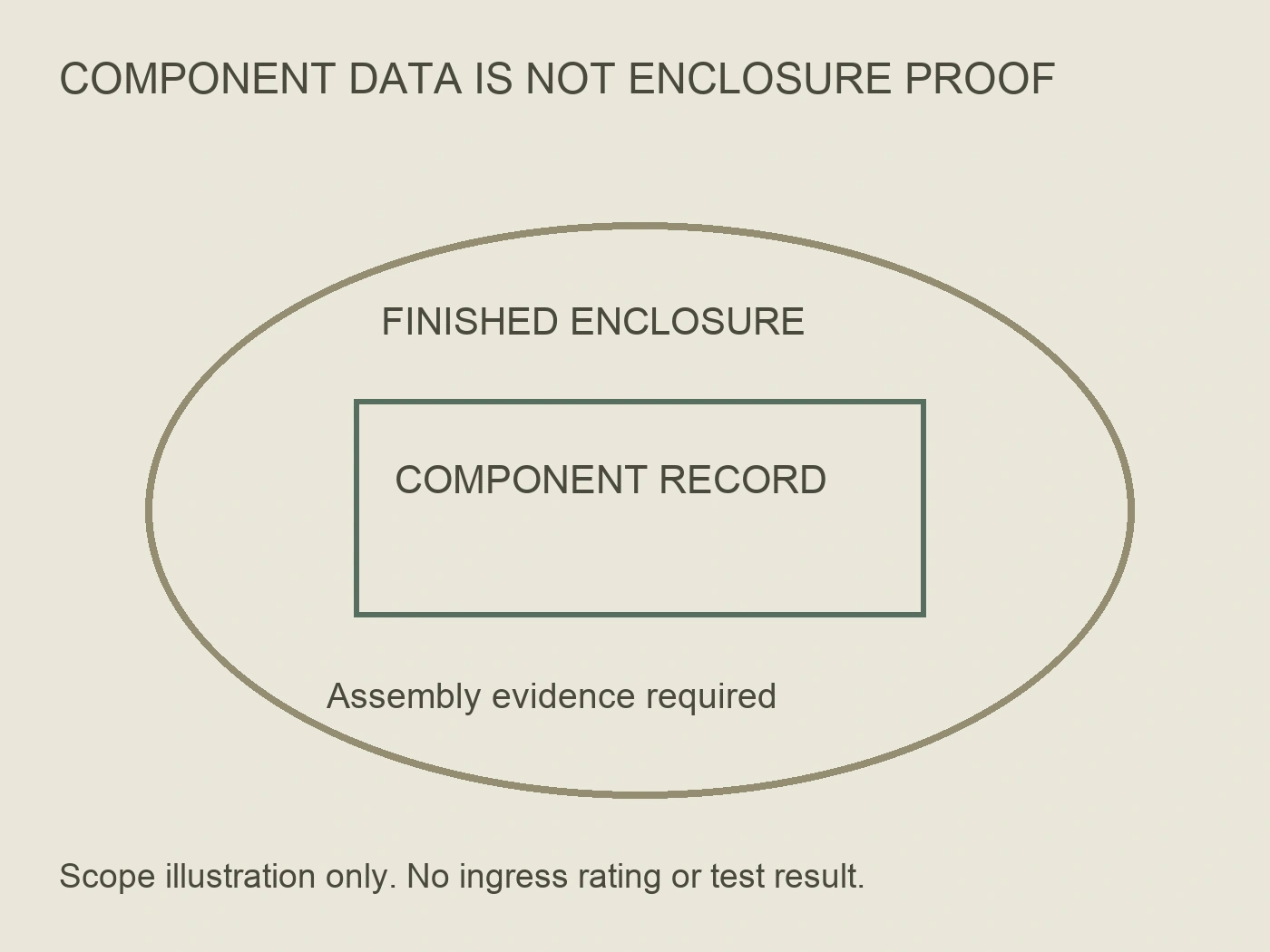
The enclosure designer should identify how the complete assembled equipment's protection is established after openings and connectors are incorporated. A connector datasheet remains useful, but it is not automatically a complete-enclosure test report.
Request the evaluated configuration, relevant assembly conditions and the evidence supporting the claimed enclosure performance. Distinguish a manufacturer's connector statement from an equipment-level verification result and from an inspection performed on a particular supplied unit.
Do not claim an assembled enclosure has passed merely because each purchased component carries a protection marking. Door seals, other cable entries and the connector mounting can introduce separate boundaries. This guide does not prescribe an improvised water-spray test or another universal validation method.
| Evidence item | What should be traceable | Reason to hold the interface decision |
|---|---|---|
| Connector specification | Exact variant and permitted mating system | Appearance offered instead of compatibility evidence |
| Mounting package | Drawing revision, wall construction and fixing criteria | Opening borrowed from a different reference |
| Sealing package | Seal identities, orientation and relevant assembled condition | Connector rating offered without mounting conditions |
| Internal termination | Exact architecture, supplied scope and integration documents | Cable-crimp example assumed to cover a PCBA interface |
| Layout review | Routing, support, access and polarity | Final assembly differs from the reviewed arrangement |
| Equipment verification | Configuration and basis for finished-enclosure performance | No evidence beyond individual component markings |
These are procurement review fields, not a claimed existing RITOKS inspection programme or normative test schedule.
Make the supplier response configuration-specific
Send the proposed enclosure construction, intended mounting location, external mate and internal connection requirements with the enquiry. Request a configuration drawing and the relevant assembly documents for the exact RTX-PVC option being considered.
If an alternative connector is offered, review the opening, fixing, sealing and internal termination again. Similar current and voltage headlines do not make it a drop-in replacement. Record which enclosure or harness drawings would change and which verification evidence remains applicable.
For a pilot assembly, agree what evidence will be reviewed before wider production. The responsible equipment designer and quality team should define the acceptance basis and authorise the result. Do not describe an unevaluated pilot as approved equipment.
Assembly and maintenance must follow the selected manufacturer's safety instructions and qualified-person arrangements. The official examples require competent personnel and warn against connection or disconnection under load. A procurement comparison does not authorise live connector work.
Resolve an enclosure proposal with a filled interface record
Consider a hypothetical combiner enclosure review, not a reported RITOKS installation. Drawing E2 specifies a shaped opening for panel option P1. Quotation Q1 names P1 but supplies only its electrical headline data. A proposed cable option C1 comes with a documented cable/contact combination, while its separate enclosure-entry arrangement is absent. The filled record therefore contains two different open decisions: P1 lacks its installed wall-interface evidence; C1 lacks the enclosure-entry evidence. Neither proposal is ready merely because one has fewer visible parts.
Suppose fictional mounting response M3 later identifies P1's opening, fixing system and permitted wall construction, but its construction does not cover the material named on E2. The drawing geometry is now supported; the wall application is not. Procurement can retain M3 as evidence for the resolved geometry instead of asking the supplier to repeat everything. The equipment designer must decide whether to change the wall design or request evidence covering E2's material. Copying the convenient opening into the existing wall would conceal the actual unresolved boundary.
The next response S2 identifies a panel gasket and its required installed condition. That closes the question of which seal the proposed panel assembly uses, not whether the complete enclosure achieves its claimed protection. Record the gasket identity under the panel interface and retain the equipment-level result as a separate open field. This distinction changes the purchase decision: ordering the documented gasket is sensible once its scope matches the design, but describing the modified enclosure as protection-approved still lacks supporting evidence.
Meanwhile, suppose C1's supplier provides entry package G4 for the intended wall construction and cable, and the equipment reviewer finds the arrangement compatible with the controlled layout. C1 can become the preferred proposal for that reviewed design even though P1 originally looked more convenient. The decision is conditional on the specific package, not a claim that cable mounting is generally superior. It can reverse if P1 later obtains matching wall and finished-equipment evidence, or if C1's approved entry creates an access problem in the final layout.
Internal termination stays independently visible. Fictional drawing I2 describes P1 as a cable-contact receptacle, while an earlier purchasing note called it a board connector. Amend that note before releasing the order; do not ask production to interpret which description controls. If a board interface is actually required by the equipment design, I2 demonstrates a scope mismatch rather than an acceptable substitute. A mechanically supported mounting proposal can still be electrically or architecturally wrong behind the wall.
The completed decision note names E2, M3, S2, G4 and I2, records which questions each answers, and states which proposal is preferred for the current configuration. These identifiers and supplier responses are invented teaching examples, not manufacturer documents or test results. If P1 is replaced by P2, reopen only the fields whose opening, fixing, sealing or internal connection depend on that variant. Retain unrelated accepted equipment information, but never extend P1's interface evidence to P2 on a similar photograph. This makes a later substitution review narrower and more reliable than a blanket request to confirm everything again.
References
- Stäubli. (n.d.). MA299: MC4-Evo 2 panel-receptacle assembly instructions. Specific mounting and sealing example; dimensions not transferred. Accessed October 2, 2026.
- Stäubli. (n.d.). MA231: MC4 cable-connector assembly instructions. Cable selection, gland and assembly-check scope. Accessed October 2, 2026.
- Phoenix Contact. (n.d.). PV-FT-CM-C-4-1000-RD: Front-mounted device connector. Specific panel-feed-through/cable example and safety notes. Accessed October 2, 2026.