
DC Fuse Holders · Technical Explainer
Square-Body DC Fuse Bases: Checking Bolt Patterns and Contact Pressure
Quick answer
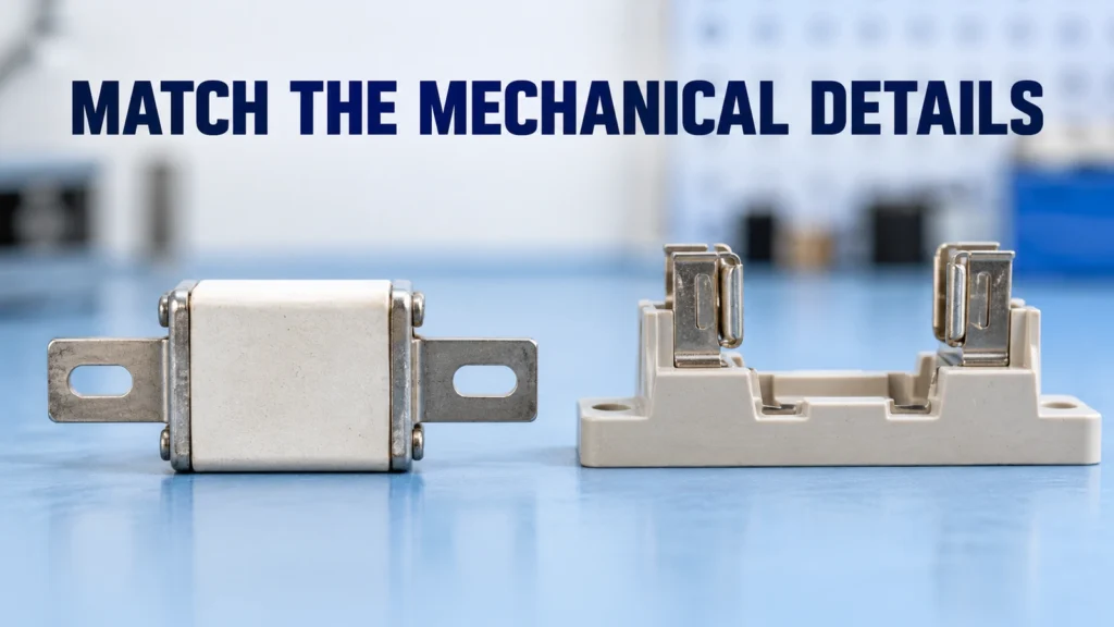
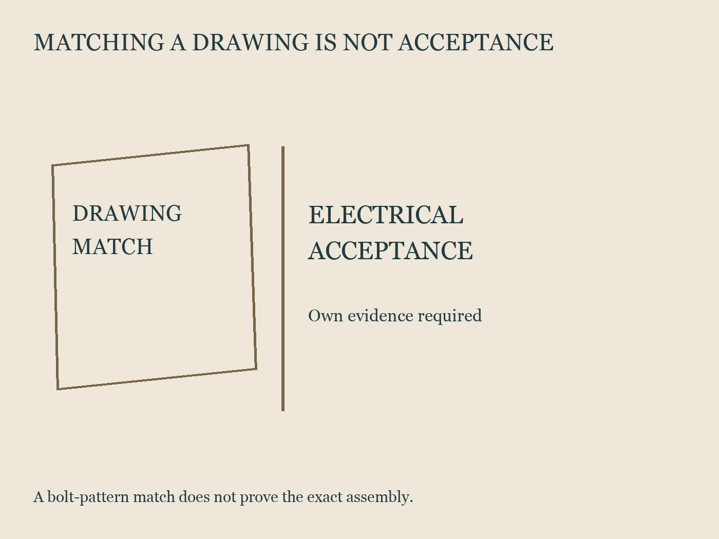
A square-body DC fuse base should be accepted against an identified fuse link, the applicable connection instructions and the complete assembly design. Matching a bolt pattern is one check, not proof of electrical compatibility or an approved contact joint. The practical procurement task is to bring the fuse, base and conductor interface into one controlled set of documents.
This guide develops that review record. It does not supply installation torque, modify contact surfaces or approve an undocumented fuse-and-base combination. Actual assembly and maintenance belong under the equipment's approved instructions and qualified electrical procedures, including the appropriate isolation arrangements. No generic illustration in a purchasing guide replaces those instructions.
Put three interfaces on the same review sheet
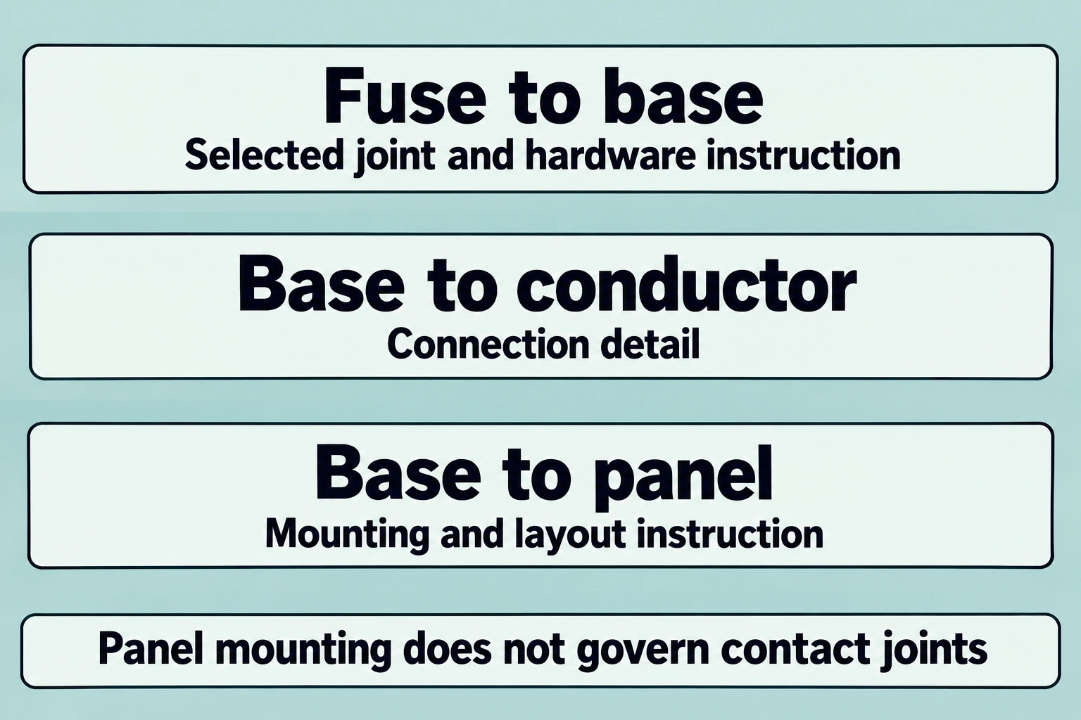
The review concerns the fuse-to-base connection, the base-to-conductor connection and the base-to-panel mounting. These are separate questions even when they appear together in an assembly drawing. An answer about one joint should not be copied into another joint's approval column without an explicit documentary basis.
Begin with the exact fuse reference and the exact base reference. Ask the supplier which drawing revisions apply to the quotation. Then identify the busbar, cable termination or other conductor arrangement proposed for the base. A fuse drawing by itself does not explain an independently manufactured conductor interface.
The following worksheet is an original procurement aid. It is not a list of approved dimensions or a substitute for the supplier's drawings.
| Interface | Information to align | Evidence requested |
|---|---|---|
| Fuse to base | Contact style, fixing locations and supported fuse identity | Matched drawings and written application confirmation |
| Base to conductor | Terminal arrangement and approved conductor connection | Connection instructions and assembly detail |
| Base to panel | Mounting reference and access envelope | Mounting drawing and panel layout |
| Fuse replacement | Access and permitted replacement references | Service instructions and spare-parts schedule |
| Auxiliary indication | Optional indicator or switch interface | Exact accessory compatibility documentation |
Give every open question an owner. The fuse supplier may own the fuse drawing, the base supplier its connection instructions and the panel builder the assembly detail. Naming those owners avoids an unanswered interface being passed between suppliers until the purchase date.
Next step: browse published DC fuse holders and the related DC fuse links. Ready to quote? Send your requirements to RITOKS.
Compare drawings with a common reference view
A bolt pattern can be described correctly yet compared incorrectly if the drawings use different views or reference points. Record the view, units and dimension origin before marking two patterns as matching. Use the complete drawings rather than a sales photograph or a cropped dimensional sketch.
Eaton's published 170M3018 product page identifies a bolted-tag contact style and a DIN 43653 designation for that specific fuse. This illustrates why the product's detailed interface description matters beyond “square body.” It does not identify a compatible RITOKS base or establish a universal mounting pattern. Eaton 170M3018 product page.
For the proposed pair, ask whether the fixing centers, contact geometry, available engagement and surrounding envelope have been reconciled. Where tolerances are supplied, keep them visible in the comparison. Where they are not supplied, request clarification instead of replacing them with measurements taken from an unscaled image.
Maintain a distinction between a dimension discrepancy and a missing dimension. A discrepancy can be sent back as a marked drawing question. A missing dimension needs the responsible supplier to provide it. Both may prevent approval, but treating them separately gives the supplier a precise action.
Include the installed orientation and adjacent components in the panel review. A nominally matching pair may still need an assembly-specific assessment of access, covers and conductor routing. This article provides no clearance values. Those values must come from the applicable equipment design and instructions.
Identify the instruction that controls each contact joint
Contact pressure is not established by guessing a tightening torque from bolt diameter. Ask which exact instruction applies to the joint and what hardware and connection conditions it assumes. Record that instruction beside the joint it governs, rather than placing one unlabeled torque value on the whole assembly drawing.
Eaton's high-speed fuse guide relates contact quality to electrical and thermal behavior. For its described special fuse holders, it directs users to the holder specification for tightening; it also warns against fuse-to-busbar misalignment stresses. These are bounded Eaton application statements, not torque or surface-treatment instructions for RITOKS products. Eaton application guide, Appendix 3.
The review record should identify the fastening location, instruction revision, specified hardware and any stated connection conditions. If fuse and holder documents appear to conflict, request a resolved combination instruction from the responsible parties. Choosing whichever value seems stronger does not resolve the conflict.
Do not treat lubrication, washer choice or contact-surface changes as harmless assembly preferences. This guide specifies none of those actions. Ask the supplier to identify the approved arrangement and preserve it in the bill of materials. An unrecorded change makes later review of the fitted joint much harder.
A document can also contain separate values for mounting a base and securing a conductor. Labeling the joints individually prevents a panel-mounting instruction from being mistaken for a live contact-joint instruction. That distinction is especially useful when several teams use the same assembly drawing.
Keep physical fit separate from electrical acceptance
A drawing comparison answers whether the proposed components appear mechanically consistent. Electrical acceptance requires the responsible engineer to review the applicable DC duty and the complete assembly. A shared product family description, mounting style or nominal rating should not automatically close both review columns.
Use the RITOKS DC fuse holder category to identify a proposed base and the separate DC fuse link category to identify the proposed protective element. The category relationship does not prove that every listed base accepts every listed link.
Ask the supplier to provide the applicable combination information for the selected parts and the intended DC application. The request should explain the assembly, not merely ask “will it fit?” Keep voltage duty, fuse identity, connection arrangement and relevant environmental assumptions in the engineer's review scope.
The following register keeps the conclusions distinct. The rows are questions to close, not claimed performance results.
| Review conclusion | Required identification | Useful status wording |
|---|---|---|
| Drawing match | Both references and revisions | Reviewed match or unresolved discrepancy |
| Contact-joint arrangement | Joint instruction and hardware | Approved arrangement or clarification needed |
| Electrical application | Exact pair and DC duty | Accepted within stated conditions or unconfirmed |
| Panel integration | Assembly drawing and configuration | Reviewed layout or integration question open |
| Replacement permission | Approved spare reference | Permitted replacement or reassessment required |
Avoid a single green “compatible” mark when only the dimensional check has been completed. Record the specific completed step. That makes a partly reviewed quotation usable without allowing it to masquerade as a finished engineering approval.
Review a proposed substitution without losing the original basis
A substitution review should compare the proposed part with the approved combination, not merely with the part being removed. Keep the original drawings, instructions and acceptance conditions available while reviewing the alternative. The reviewer needs to know what is being preserved and what has changed.
Consider a hypothetical purchasing case: a replacement fuse has apparently matching fixing centers, but its contact description differs from the approved drawing. No installation or test result is assumed. Procurement should forward the difference for a combination review rather than accept it because the bolt positions look familiar.
The same approach applies to a new base with a revised conductor terminal. Even if it accepts the original fuse, the conductor interface may need a separate decision. Record whether the quotation includes the originally specified hardware and any covers or accessories that formed part of the accepted assembly.
Make approval conditions visible on the replacement schedule. If only a particular fuse reference is accepted, do not reduce that entry to an amperage and a body size. If alternatives are permitted, preserve the document that establishes those alternatives and any restrictions attached to them.
An unresolved substitution can remain a quotation option without becoming an approved spare. This distinction lets procurement collect prices while keeping the technical decision with the responsible reviewer. It is more precise than rejecting every alternative or accepting one through an informal verbal agreement.
Hand over a record that remains usable during service
A useful handover connects the fitted parts, the approved instructions and the relevant assembly revision. It should let a maintenance planner identify the right replacement before opening a purchase request. A photograph can help identify the installation, but it cannot replace part references and connection documentation.
The handover should also distinguish initial assembly acceptance from later inspection or service work. This article does not prescribe retightening intervals, live inspection procedures or post-fault reuse. Those questions must follow the exact equipment instructions and the owner's electrical maintenance arrangements.
Record any outstanding information explicitly. If the manufacturer has not confirmed a proposed combination, identify it as unconfirmed. If a revised drawing is required, name that drawing. Clear status wording helps prevent an incomplete procurement file from being used as a completed service instruction.
Complete a substitution record across the three joints
Consider a hypothetical panel proposal containing fuse F1, base B1 and conductor arrangement C1 under assembly drawing A3. Those references are invented, not Eaton or RITOKS models. The record separates joint J1 between fuse and base, J2 between base and conductor, and mounting boundary J3 between base and panel. It also keeps the electrical application decision separate from all three drawing comparisons. This establishes what a later document can resolve without assuming that every fixing belongs to the same fastening instruction.
Supplier response D2 reconciles the fixing locations and reference views for F1 and B1. The engineer accepts that defined dimensional comparison, but D2 does not identify the approved J1 contact hardware or joint instruction. The filled status is therefore drawing match accepted, contact arrangement unresolved. A photograph showing a fastener passing through each hole would not close the second field. Contact quality concerns the documented joint as a whole, not merely the ability to align two parts, and this example reports no assembled trial or measured pressure.
Next, the panel builder provides mounting document M4 for J3. It names the base-to-panel arrangement under A3, but its fastening requirement does not govern J1 or J2. Procurement can close the mounting-document identity while continuing to request the contact-joint instructions. Copying M4's requirement onto both electrical joints would turn a useful resolved boundary into unsupported assembly guidance. The narrow record instead names which instruction belongs where and leaves an explicit blank decision only where evidence is genuinely missing.
Assume response H2 subsequently identifies an accepted J1 hardware set and instruction for the F1/B1 combination. The contact arrangement can now be reviewed on that basis. If the quotation supplies a different hardware set H3, the discrepancy remains open even though D2's geometry has not changed. The reviewer should reconcile H3 with the approved instruction rather than treating washers, surface condition or hardware substitutions as interchangeable preferences. No torque, pressure, coating change or lubrication method is provided here; those actual requirements must belong to the exact combination documentation.
A competing base B2 may appear to offer the same fuse interface, while its conductor terminal differs from B1. Suppose fictional comparison D5 supports F1's interface with B2, but the existing conductor drawing C1 does not describe B2's revised terminal. The filled outcome is useful partial evidence: J1's drawing question is supported for the alternative, while J2 needs the changed conductor-interface detail. This can reverse the apparent purchase preference once integration cost and documented scope are understood. It is not a blanket rejection of B2 or automatic approval of B1; the missing question is specifically how the proposed conductor arrangement belongs to the alternative base.
An electrical-application response E2 remains another independent record. Assume it covers the original F1/B1 arrangement under stated project conditions but lists no alternative base or fuse. It cannot be extended to B2 merely because D5 supports mechanical geometry. Equally, a complete J1/J2/J3 drawing package cannot supply E2's missing application coverage. A reviewer may prefer the original documented arrangement while requesting evidence for the alternative, or accept the alternative after the responsible parties provide matching application and joint information. The decision follows the completed scope rather than the square-body label.
Service access can change that comparison again. If the reviewed panel layout allows the accepted replacement arrangement for B1 but the B2 proposal obstructs the access required by its instructions, resolve the layout before releasing B2. Do not invent a universal clearance or demonstrate removal on energized equipment. Keep the issue tied to the selected service instruction and A3's layout. A change in access can matter even when the electrical duty and fuse-contact drawings are otherwise adequately documented.
The final schedule should name the accepted fuse, base, conductor arrangement, hardware set, joint instructions and application conditions. Retain D2's completed drawing comparison instead of requesting it repeatedly, and show exactly which B2 or H3 substitution question remains open. All documents and outcomes above are hypothetical; none establishes a real CFPV-H/DNESS pair, a universal DIN pattern or performed assembly test. A future replacement that changes only the fuse must be checked against its affected interface and application scope; a changed conductor terminal opens a different review. This gives procurement and maintenance a usable accepted-parts boundary without collapsing partial progress into an unqualified compatible mark.
References
- Eaton. (n.d.). Bussmann series high-speed fuses application guide (BR132015EN, Appendix 3). https://www.eaton.com/content/dam/eaton/products/electrical-circuit-protection/bussmann-iec-high-speed-semi-conductors-fuses/eaton-bussmann-series-high-speed-fuses-application-guide-br132015en-en-us.pdf
- Eaton. (n.d.). 170M3018: Bussmann series high-speed square-body fuse. https://www.eaton.com/us/en-us/skuPage.170M3018.html