
Cầu dao thu nhỏ (MCB) của DC · Giải thích kỹ thuật
How to Read a DC MCB Datasheet: Ratings and Conditions

Quick answer
Read a DC MCB datasheet in this order: first find the standard the ratings are declared under (IEC 60898-2 or IEC 60947-2, or UL 489 / UL 1077 for North America), then the rated DC voltage together with the pole wiring that achieves it, then the DC breaking capacity and the voltage it was stated at, then the rated current and the reference temperature, then the trip curve, and finally polarity and terminal data. A value only means something when it is read with its conditions. "1000 V DC, 6 kA" without a standard, wiring diagram and test voltage is a marketing line, not a rating you can design with.
Many DC breaker datasheets fit on one page and look similar. The differences that matter sit in small print: which standard was used, which poles must be connected in series, and which temperature the rated current refers to. Buyers who compare only the headline numbers often discover at commissioning that two "equivalent" devices were rated under different conditions.
This guide walks through each block of a typical DC MCB datasheet, explains what the value means, and lists the condition that must be attached to it. Examples use rounded or hypothetical numbers. Always use the exact datasheet and wiring diagram for the order code you will buy.
Start with the standard, because it defines every other value
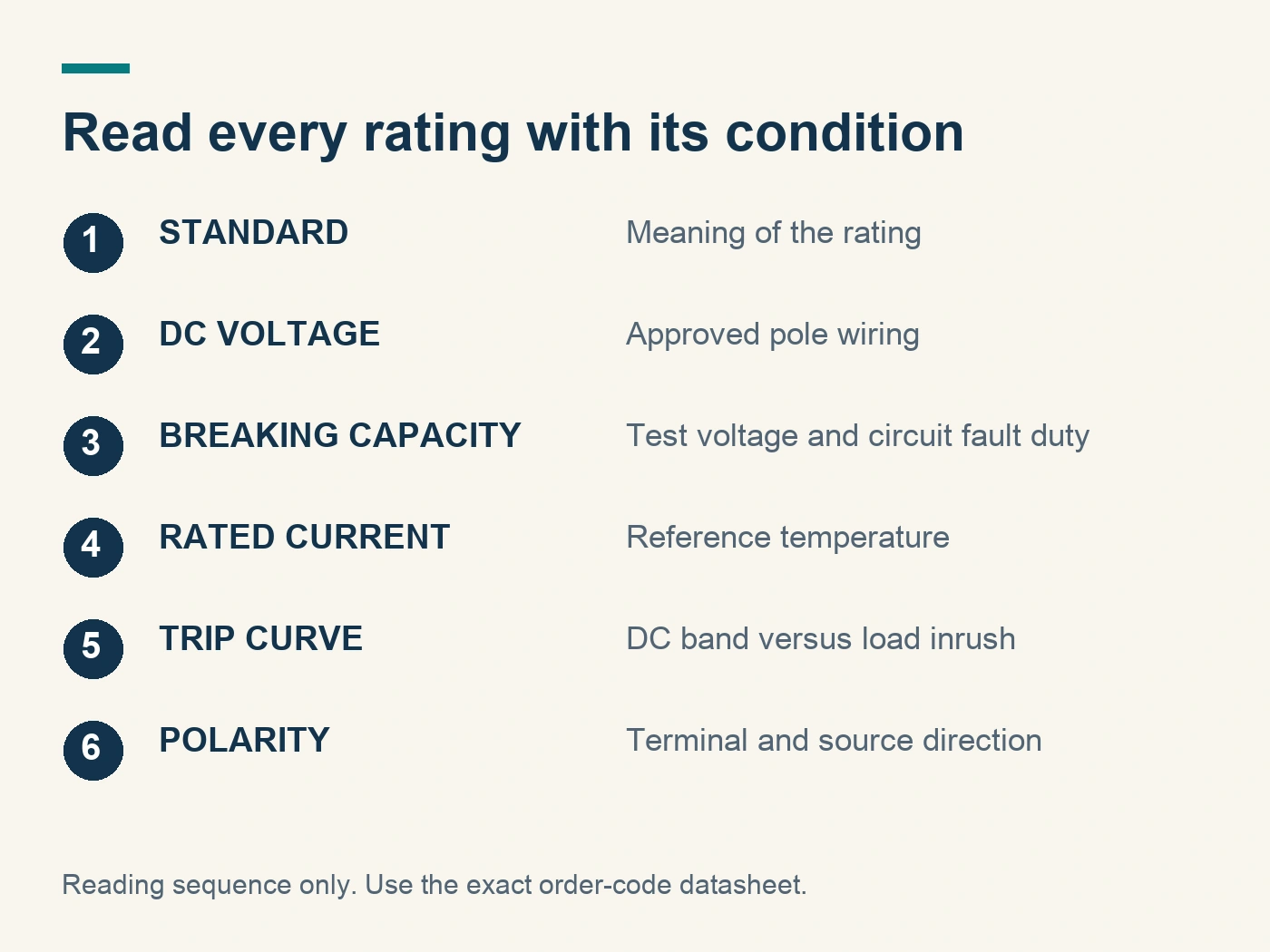
The standard tells you how each rating was tested and what the symbols mean. Two IEC standards cover most DC MCBs.
IEC 60898-2:2016 covers circuit-breakers for household and similar installations that are also suitable for DC. According to the IEC webstore abstract, it applies to single-pole devices up to 220 V DC and two-pole devices up to 440 V DC, with rated current up to 125 A and rated DC short-circuit capacity up to 10 000 A. It is read together with IEC 60898-1:2015, and the 2016 edition introduced the test Icn1. If a datasheet claims IEC 60898-2 for a 1000 V DC two-pole device, the claim falls outside that published scope and should be queried.
IEC 60947-2 covers circuit-breakers for industrial use, operated by instructed or skilled persons. The current sixth edition (2024) covers devices up to 1000 V AC or 1500 V DC. Many high-voltage DC MCBs for PV and battery systems declare their ratings under this standard. The previous edition's amendment added Annex P for circuit-breakers used in PV applications.
In North America, UL 489 covers molded-case circuit breakers, UL 489B covers molded-case breakers and switches for PV systems up to 1500 V DC, and UL 1077 covers supplementary protectors. A UL 1077 supplementary protector is not a branch-circuit breaker, even when it looks like one. Which of these a buyer should request depends on the destination market and the installation code adopted there.
Write the declared standard and edition next to every rating you copy from the datasheet. If the datasheet lists several standards, ask which values belong to which standard.
Rated voltage: always read it with the wiring diagram
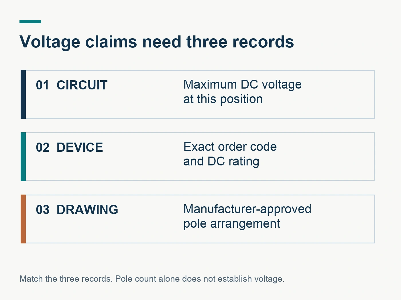
The rated operational voltage Ue on a DC MCB datasheet usually depends on how the poles are connected. A common pattern is a table or footnote that gives one voltage per pole and a higher voltage when two or more poles are wired in series. The Schneider Electric Electrical Installation Guide gives the PV example that breaking at 1000 V needs four poles in series, two per polarity.
When you read the voltage block, look for three things:
- The voltage per pole and the voltage for the full device.
- A connection diagram that shows exactly which terminals are bridged and where the source and load connect.
- Whether the voltage refers to the system's maximum voltage, such as PV open-circuit voltage at the lowest temperature, or a nominal value.
A hypothetical 2P datasheet might show 500 V DC per pole and 1000 V DC with both poles in series in one conductor. That device is not a 1000 V DC breaker for a circuit where each pole switches a separate polarity. The diagram decides which case applies. Our guide to 2-pole vs 4-pole DC circuit breakers covers the architecture choice.
Also check the rated insulation voltage Ui and the rated impulse withstand voltage Uimp where they are listed. They describe insulation coordination, not breaking ability, and should not be read as a higher operating voltage.
Breaking capacity: find the symbol, the value and the test voltage
Breaking capacity tells you the highest prospective fault current the device can interrupt under the standard's test conditions. The symbol depends on the standard.
| Symbol | Tiêu chuẩn | Meaning in plain terms | What to check |
|---|---|---|---|
| Icn | IEC 60898-1/-2 | Rated short-circuit capacity | Value at the stated DC voltage and pole wiring |
| Icn1 | IEC 60898-2 | Additional short-circuit test value added in the 2016 edition; defined with IEC 60898-1 | Its definition in the standard, whether it is listed, and at which voltage |
| ICU | IEC 60947-2 | Rated ultimate short-circuit breaking capacity | Value at the stated DC voltage; device may not be reusable after this test |
| Ics | IEC 60947-2 | Rated service short-circuit breaking capacity | Usually a percentage of Icu; device remains serviceable afterwards |
The most common reading error is taking an AC breaking capacity as a DC value. A breaker marked 10 kA on the AC table may have a lower or no DC value. Another error is taking a DC value stated at a low voltage and applying it at a higher one. The DC breaking capacity must be read at a voltage equal to or above the maximum voltage of your circuit, with the same pole wiring.
Then compare the value with your circuit. At a battery position the prospective fault current can be high. At a PV string in a combiner box, the device on a faulted string can carry reverse current fed by the other parallel strings, up to about (N_s − 1) × I_SC_MAX, so the string count matters as much as one string's short-circuit current. Our guide to DC MCB breaking capacity explains how to get the prospective fault current and what evidence to request.
Rated current and the reference temperature
Rated current In appears as a list of values, such as 6, 10, 16, 20, 25, 32, 40, 50 and 63 A. Each value is defined at a reference ambient temperature stated in the datasheet. IEC 60898 products commonly use 30 °C and IEC 60947-2 products may use a different reference, so read the footnote instead of assuming.
If the breaker will sit in a warm enclosure, look for a derating table or curve. A hypothetical table might show that a 32 A device carries about 29 A at 50 °C. Grouping several devices side by side on a DIN rail can reduce the permitted current further. Our article on MCB ambient temperature and grouping derating shows what to request when the table is missing.
For PV string protection, the selected current must also fall inside the window set by the installation rules, which in IEC 60364-7-712:2017 was more than 1.5 and less than 2.4 times the module short-circuit current. Derating can push a device out of that window, so check both together.
Trip curve: read the DC version
The time-current curve shows how fast the device trips at a given multiple of rated current. The thermal part of the curve is similar for AC and DC. The magnetic or instantaneous part can differ, because a DC current does not have AC peaks. Many manufacturers publish a separate DC instantaneous range or a correction factor.
When reading the curve:
- Check whether it is labelled for DC, or whether a footnote gives a DC multiplier for the instantaneous band.
- Note the curve letter or characteristic and the instantaneous range in multiples of In.
- Compare the instantaneous band with converter or capacitor inrush at that position, so that normal switching does not trip the device.
- Compare the thermal band with the cable's permitted current and short-circuit limits. Our guide to DC cable protection studies shows how to overlay the two.
If the datasheet only shows an AC curve, ask for the DC curve before using the device for coordination.
Polarity and terminal markings
Look for plus and minus symbols, arrows, or "line" and "load" markings on the terminal drawing. These indicate a polarized device with a required orientation. A datasheet that says "non-polarized" should still include a statement of the conditions under which that applies, such as voltage and wiring. Our article on polarized vs non-polarized DC MCBs explains how to verify each claim.
In battery systems, current flows in both directions during normal operation. A polarized device needs a documented orientation that is valid for every source that can feed a fault at its position.
Mechanical and installation data
The remaining blocks are easier to read but still affect selection:
- Terminal capacity: the conductor cross-section range and type, such as rigid or flexible, plus the tightening torque. Check it against the cable size chosen for the circuit.
- Mounting: 35 mm DIN rail is standard for MCBs. Check the device width in modules for panel layout.
- Endurance: the number of mechanical and electrical operations. Electrical endurance is often stated at rated current and voltage; a DC figure can be lower than the AC figure.
- Protection degree and pollution degree: these influence the enclosure needed. The Electrical Installation Guide notes that pollution degree 2 switchgear in a 1000 V PV system calls for an enclosure of at least IP5x.
- Operating temperature range: separate from the reference temperature for rated current.
- Accessories: auxiliary contacts, alarm contacts and shunt trips, with their own ratings.
A worked reading of a hypothetical datasheet
The values below are invented to show the reading order. They do not describe any real product.
| Datasheet line | How to read it | Question to ask |
|---|---|---|
| Standard: IEC 60947-2 | Industrial breaker; Icu/Ics symbols apply | Which edition? Does the certificate name this order code? |
| Ue: 1000 V DC (2P, series) | 1000 V only with both poles in one conductor | Is the series wiring diagram attached? Does it fit our earthing? |
| Icu: 6 kA at 1000 V DC | DC breaking value at the system voltage | What is Ics? What time constant did the test use? |
| In: 6–63 A at 30 °C | Rated current at 30 °C ambient | What is the derating at our enclosure temperature? |
| Curve: C, DC instantaneous 7–15 In | DC magnetic band differs from AC | Does converter inrush fall below this band? |
| Polarity: marked + / − | Polarized device | Is the orientation valid for charge and discharge? |
Reading the table row by row turns a one-page datasheet into a set of specific questions. If any answer is missing, record it as open instead of assuming the most favourable value.
Five datasheet red flags
- No standard named, or a standard named whose scope does not cover the stated voltage.
- A DC voltage with no pole wiring diagram.
- A breaking capacity with no voltage, or only an AC table.
- A certificate that names a series but not the order code offered.
- Rated current with no reference temperature and no derating data.
None of these proves the device is unsuitable. Each one means the datasheet cannot yet support the design decision.
Buyer questions
Is a higher kA value always better?
Only when it is stated at your voltage and wiring under a comparable standard. A 10 kA value at 250 V DC does not establish the breaker's capacity at 800 V DC. Compare like with like, and match the value to the real fault current at the position.
Can I use an AC MCB datasheet to choose a DC device?
No. AC and DC ratings are tested separately, and an AC-only device may have no declared DC ability. Use a datasheet that states DC ratings for the exact model.
What should I send a supplier if the datasheet is incomplete?
Send the circuit's maximum DC voltage, prospective fault current, current direction, earthing arrangement, cable size and enclosure temperature, and list the missing datasheet values. Our Danh sách kiểm tra yêu cầu báo giá (RFQ) cho MCB DC gives a complete template.
Where can I see how RITOKS presents its DC MCB data?
Cái RTS-DC63-500 2P DC MCB page lists its DC 500 V rating, nine current options, 6 kA DC breaking capacity and IEC 60947-2 reference, and the RTS-DC63-1000 page lists its 500–1000 V DC scope. Request the order-code datasheet and wiring diagram with your quotation. All families are on the DC miniature circuit breakers category page.
Finish with a filled reading sheet
Copy each datasheet value into a sheet with its standard, voltage, wiring and temperature next to it. Mark anything missing as open. Then compare the sheet with your circuit: voltage at the position, fault current, current direction, cable and enclosure. A breaker is ready for selection when every row has both a value and its condition.
Tài liệu tham khảo
- International Electrotechnical Commission. (2016). IEC 60898-2:2016 Circuit-breakers for overcurrent protection for household and similar installations – Part 2: Circuit-breakers for AC and DC operation. Retrieved October 23, 2026, from https://webstore.iec.ch/en/publication/25675
- International Electrotechnical Commission. (2024). IEC 60947-2:2024 Low-voltage switchgear and controlgear – Part 2: Circuit-breakers. Retrieved October 23, 2026, from https://webstore.iec.ch/en/publication/66277
- Schneider Electric. (2026). PV System: how to ensure safety during normal operation. Electrical Installation Guide. Retrieved October 23, 2026, from https://www.electrical-installation.org/enwiki/PV_System:_how_to_ensure_safety_during_normal_operation
- RITOKS. (n.d.). 2P DC miniature circuit breaker, 500V, 6–63A. Retrieved October 23, 2026, from https://ritoks.com/products/2p-dc-miniature-circuit-breaker-500v-6-63a/