
Bridge Rectifier Modules · Technical Explainer
Bridge Rectifiers in Industrial DC Power Supplies
A bridge rectifier for an industrial power supply converts an AC source into unregulated DC for a downstream bus, filter or load. Selection must account for the actual source, load waveform, capacitor charging current, ripple, abnormal conditions, conduction loss and cooling path. A headline current or voltage rating cannot describe the whole application.
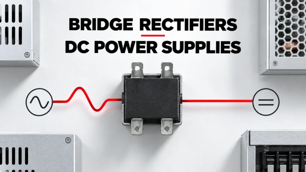
This application guide defines the information needed to review a bridge rectifier module. It does not design an industrial power supply, calculate an approved MDS module operating point, or prescribe capacitors, protection, isolation, busbar layout or thermal hardware for an unknown circuit.
Decision Inputs at a Glance
| Decision input | Buyer must confirm | Evidence required |
|---|---|---|
| AC source | Phase count, voltage range, frequency and impedance | System single-line and source data |
| DC demand | Load profile, output range and downstream topology | Measured or calculated bus current waveform |
| Charging stress | Capacitor bank, precharge and inrush behavior | Circuit simulation or test evidence |
| Semiconductor loss | Current waveform and forward characteristics | Exact-model loss method |
| Thermal path | Baseplate, interface, heatsink, ambient and airflow | Complete thermal calculation and mounting instructions |
Define the Rectifier Position in the Power Supply
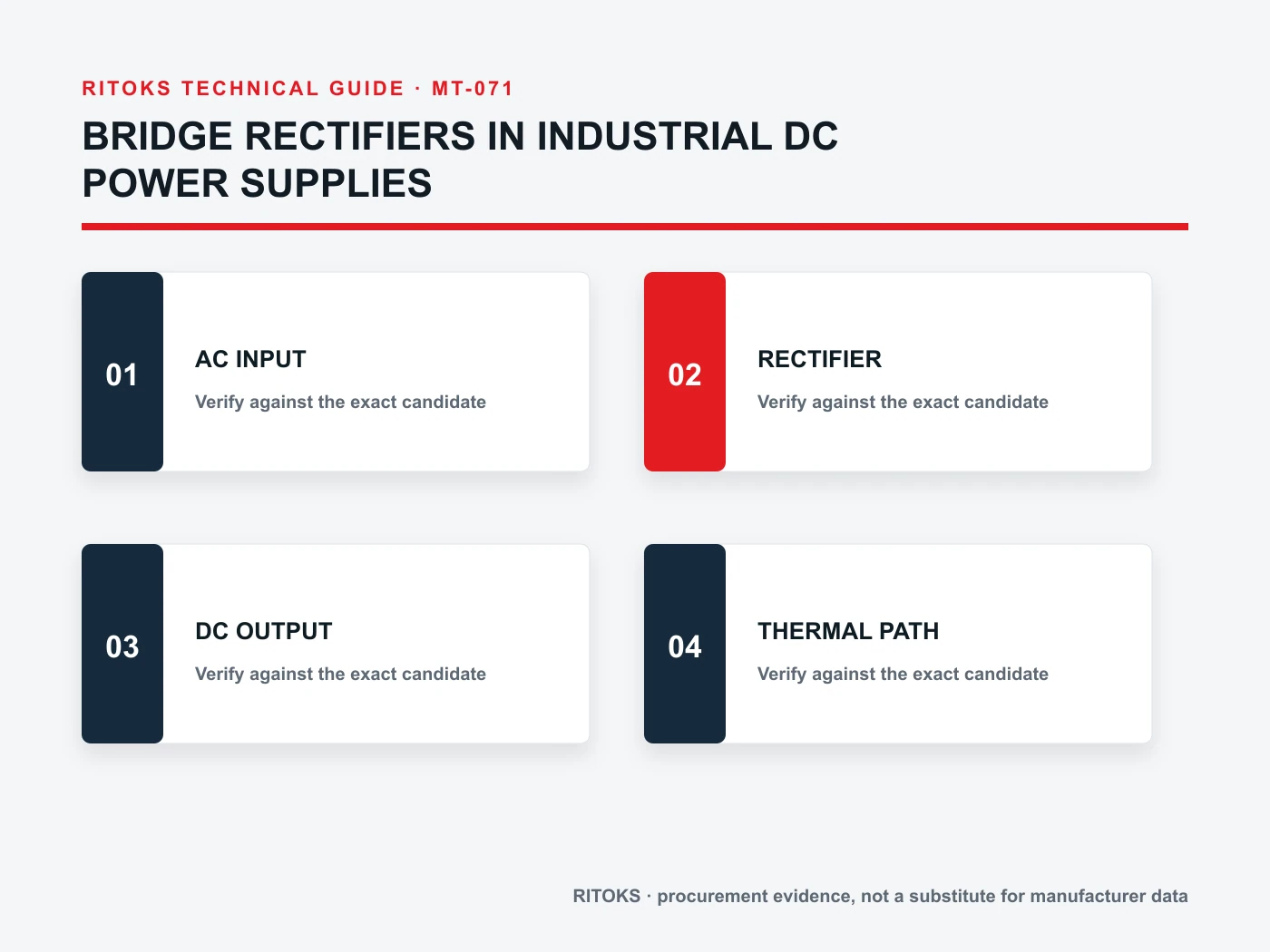
Show the AC source, bridge, DC bus, filtering, downstream converter or load, and protective devices on a functional diagram. State whether the bridge is single-phase or three-phase and whether it is uncontrolled or part of another controlled topology.
This boundary prevents a module family name from being mistaken for the entire supply. The rectifier does not by itself provide regulation, isolation, filtering, inrush control or downstream protection unless those functions are explicitly part of the system.
Use the Real Current Waveform
The current through bridge elements is rarely equal to a smooth DC load value. With capacitor-input filtering, conduction may occur in pulses near source-voltage peaks. Transformer impedance, capacitance, load, line condition and precharge strategy shape those pulses.
Average output current alone can therefore hide RMS and peak stress. Use an applicable calculation, simulation or measurement method and compare the resulting waveform with the exact device data under matching conditions.
Review Ripple and Bus Conditions
Define required DC bus range, allowable ripple and the behavior of the downstream load across line and operating states. Ripple is a system result involving source, rectifier, filter and load. It should not be attributed to the bridge module alone.
Also identify regeneration, stored energy or externally driven bus conditions. If reverse energy flow or unusual commutation can occur, the circuit requires a specific review rather than an assumption based on a standard diode bridge.
Account for Inrush, Surge and Fault Scenarios
Capacitor charging at startup can create a high transient current. Define precharge or inrush limiting and the sequence that bypasses it. Record supply restoration, repeated starts and any condition that reconnects a discharged bank.
Separate repetitive operating stress from non-repetitive surge data and from protective-device coordination. A surge rating is not permission to use the module as a recurring inrush limiter. The complete fault path and interrupting devices require their own evidence.
Calculate Loss and the Complete Thermal Path
Conduction loss depends on the current waveform and exact forward characteristics. Multiple devices conduct during each path through a conventional bridge, but the final method must follow the selected topology and datasheet.
Carry the loss through baseplate, interface material, heatsink and ambient conditions. Mounting pressure, surface condition, isolation, airflow and nearby heat sources can affect the result. Verify the assembled temperature at the intended duty.
Check Terminals, Polarity and Mechanical Integration
Use the exact circuit and terminal diagram for the order code. Similar module housings can contain different internal connections, and a photograph cannot prove terminal function. Define busbar or cable arrangement, conductor forces, clearances and service access.
Follow exact mounting and terminal-torque instructions. The application drawing should show polarity and phase labels, but this article intentionally avoids an installation wiring diagram because those details must come from the approved device and system design.
Build an Exact-Model Evidence File
Create one approval record for the proposed Bridge Rectifier Module order code. Put each project requirement beside the supplier document that answers it. Preserve the exact datasheet, drawing, curve, table or selection output used, including its revision or retrieval date. A category page can establish family context, but it cannot prove an exact rating, terminal arrangement or system combination.
Check that every accepted statement describes the same orderable item. Similar housings can contain different circuits, supplies, terminals, accessories or protection functions. Do not combine a family maximum from one variant, a diagram from another and an optional feature from a third. Mark unresolved fields explicitly so they remain visible in the commercial review.
Keep Project Inputs Separate From Product Evidence
The project team defines the application: source, load, duty, environment, controls, mechanical limits and required functions. The supplier identifies an exact Bridge Rectifier Module and supports it with exact documents. Neither side should fill a gap by inference from appearance, a shared family name or one matching headline value.
Freeze the application record while quotations are being compared. If the load, voltage, duty, environment, cooling method, enclosure or required output changes, issue a revised record and ask each supplier to reconfirm the candidate. Otherwise apparently comparable quotations may be answering different technical requirements.
Common Procurement Errors
- Selecting Bridge Rectifier Module from one headline rating while the application context remains incomplete.
- Using a circuit, curve, terminal drawing or performance claim from a neighboring model.
- Treating a family page or product photograph as exact technical evidence.
- Assuming an accessory, system function or coordination result is included without documentation.
- Approving a substitute without repeating the topology, rating, mounting and evidence review.
Resolve these gaps before comparing price and lead time. The reviewer should be able to trace every accepted statement either to the project requirement or to the exact candidate document. A proposal may remain commercially interesting while technically incomplete, but missing evidence must not disappear inside the quotation.
How to Compare Supplier Offers
| Comparison point | Required evidence | Do not accept |
|---|---|---|
| Review area | Required project input | Exact evidence required |
| Topology | Single/three phase and uncontrolled/controlled function | Circuit and terminal diagram |
| Current | Average, RMS, peak and waveform context | Datasheet method plus calculation |
| Transients | Inrush, surge and restart behavior | Applicable non-repetitive/repetitive limits |
| Voltage | Source range and abnormal conditions | Blocking-voltage evidence with margin method |
| Thermal | Loss, interface, sink, ambient and airflow | Complete temperature calculation |
| Mechanical | Terminals, mounting and conductors | Exact drawing and instructions |
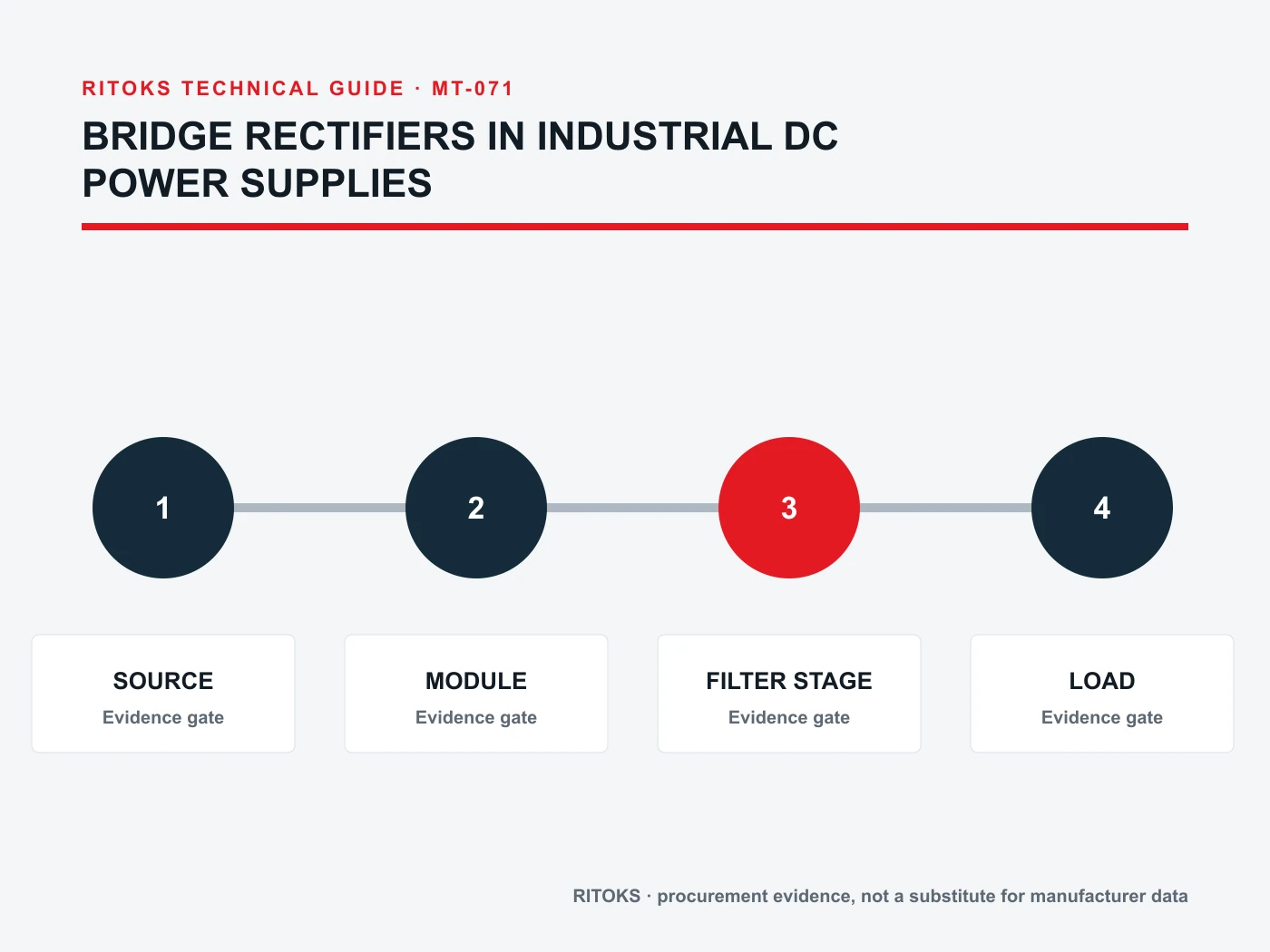
Normalize every Bridge Rectifier Module offer to the same application record. Keep document revisions, test conditions, included accessories and open questions beside each value. This makes differences in delivered scope visible and prevents a lower-cost but narrower offer from appearing equivalent to a complete solution.
Decision Workflow
- Draw the source, rectifier, DC bus and load boundary.
- Calculate or measure the bridge current waveform.
- Define ripple, capacitor bank and precharge behavior.
- List surge, restart and fault scenarios.
- Select an exact topology and voltage/current class for review.
- Calculate loss and complete thermal path.
- Verify terminals, mounting, protection and assembled temperatures.
At each step, stop when a critical application input is unknown, the quoted model is ambiguous, a required claim is supported only by another manufacturer or another order code, or the installation falls outside the available evidence. These are engineering gaps, not editorial details.
RFQ Preparation Checklist
A useful RFQ for bridge rectifier for industrial power supply is concise enough to answer and complete enough to prevent silent assumptions. Identify unknown values as questions and require a full orderable code rather than a generic family recommendation.
- Single-phase or three-phase source and voltage range
- Frequency and source/transformer impedance
- DC load profile and downstream topology
- DC bus capacitance, ripple and precharge method
- Average, RMS and peak current evidence
- Surge, restart and fault conditions
- Required internal topology and terminal arrangement
- Cooling, mounting, quantity and destination
Request the current datasheet revision and the exact scope of any certification, compatibility, coordination or performance claim. Record quantity and destination after the technical inputs so commercial terms do not obscure unresolved engineering questions.
Frequently Asked Questions
Can I select a bridge rectifier from DC load current alone?
No. The device current waveform, peak charging current, voltage conditions and cooling also matter.
Does a bridge rectifier regulate the DC output?
No. Regulation and ripple depend on the wider power-supply topology.
Is surge current a continuous operating rating?
No. Repetitive operation and non-repetitive surge conditions must be kept separate.
Related RITOKS Products and Guidance
These links provide product-family context only. A contextual link does not claim interchangeability, compatibility or an approved system combination.
Bridge Rectifier Module product category
MDS three-phase bridge rectifier modules
MDS high-current bridge rectifier modules
Technical References
These primary manufacturer sources support only the general engineering concepts described below. Their product ratings, circuit diagrams, approvals and coordination results do not transfer to RITOKS products.
Infineon, Design of Active Bridge Line Rectification for SMPS
Supports the importance of bridge conduction loss, current waveforms, abnormal conditions and thermal status in power-supply design. Its active-bridge circuit and component values do not describe RITOKS diode modules.
Semikron Danfoss, Application Manual Power Semiconductors
Supports general rectifier, thyristor, thermal-management and module-selection concepts. Semikron Danfoss device values and design examples do not transfer to RITOKS products.
Request an Exact-Model Review
Send the application requirements, exact-document questions, quantity and destination through the RITOKS contact form. An RFQ requests an exact-model review; this guide does not approve a circuit, installation or automatic substitute.